
About Lesson
Troubleshooting Connectivity Problems at the AP
discusses how to diagnose problems between a WLC and an AP that might affect wireless client connectivity.
The split-MAC architecture creates several different points where you can troubleshoot. Successfully operating the lightweight AP and providing a working BSS require the following:
- The AP must have connectivity to its access layer switch.
- The AP must have connectivity to its WLC, unless it is operating in FlexConnect mode.
Displaying Information About an AP
- First, verify the connectivity between an AP and a controller.
- The easiest approach is to simply look for the AP in the list of live APs that have joined the controller. If you know which controller the AP should join, open a management session to it. Enter the AP’s name in the search bar.
- If the search reveals a live AP that is joined to the controller, information is displayed in the Access Point View screen.
Displaying Information About an AP (Cont.)
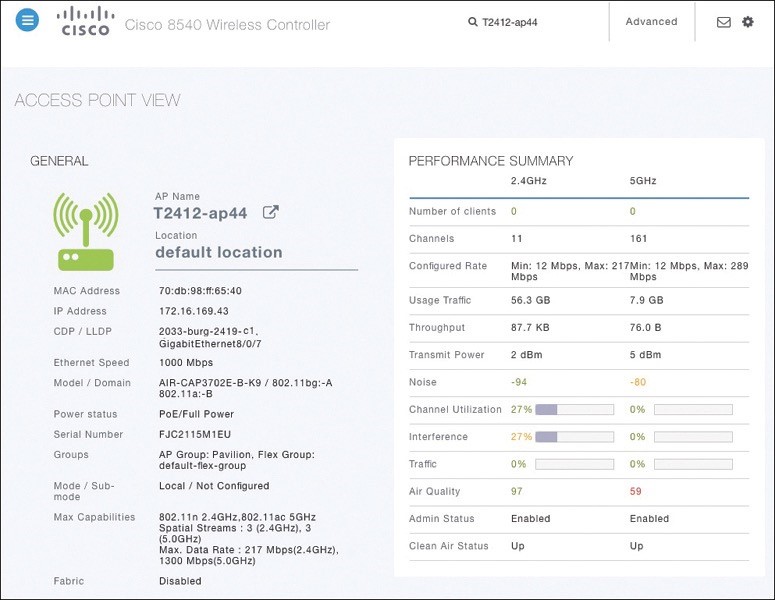
- the AP is named T2412ap4, has an IP address and a valid CDP entry that shows the switch name and port number where it is connected. The AP has a live Ethernet connection with a switch and has working PoE.
- In the right portion of the Access Point View screen, you can verify parameters related to the AP’s wireless performance and RF conditions.

Performance Summary Information
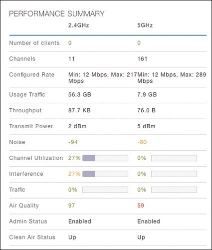
- Another important indicator is the noise level on a channel. Ideally, the noise level should be as low as possible, usually around −90 or −100 dBm, so that 802.11 signals can be received intelligibly and accurately.
- Figure lists the 5 GHz channel 161 as having a high noise level of −80 dBm—something that is not normal or ideal.
Performance Summary Information
- The channel information also shows an index of air quality. This is a measure of how competing and interfering devices affect the airtime quality or performance on a channel, presented as a number from 0 (worst) to 100 (best).
- The AP shows the air quality of channel 11 as 97, which is very good. However, channel 161 is 59, which is of concern.
- You can scroll further down in the AP View screen to see detailed information about the AP including a list of clients it is supporting, RF troubleshooting information, clean air assessments, and a tool to reboot the AP.
Displaying Information About RF Interferers
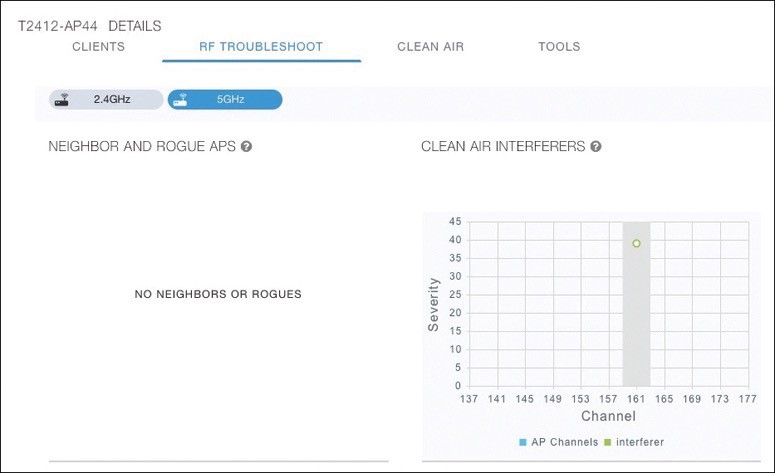
- the RF Troubleshoot tab has been selected to display interferer data for the channels in the 5 GHz band.
- There are no interfering neighbor or rogue APs, but there is a clean air interferer in channel 161 the channel that the AP is using.
Displaying Information About Clean Air
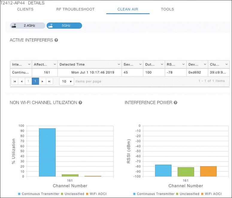
- Select the Clean Air tab to see more details about the interfering devices that have been detected.
- In Figure 21-17, the Active Interferers table lists one continuous transmitter device with a severity level of 45, a duty cycle of 100%, and an RSSI value of −78 dBm.
- The severity level indicates how badly the interferer is affecting the channel. The duty cycle represents the percentage of time the device is actually transmitting.
Displaying Information About Clean Air

- The two bar graphs represent the percentage of time the device is using the channel and the received signal strength level of the device.
- If users are complaining about problems when they are around this AP, you should focus your efforts on tracking down the continuously transmitting device.
- The best outcome is if the device can be disabled or moved to an unused channel. If not, you will likely have to reconfigure the AP to use a different channel to move away from the interference.
Other useful information:
Join the conversation