Switched Port Analyzer (SPAN) Technologies
examines the benefits and operations of SPAN, RSPAN, and ERSPAN.
When the problem appears to be a L2 issue, there are a few options:
- Insert a splitter between the devices.
- Configure the network device to mirror the packets.
- Insert a switch between the two devices and then configure the switch to mirror the transient traffic to a traffic analyzer.
Switches provide the SPAN, which makes it possible to capture packets using the second two options.
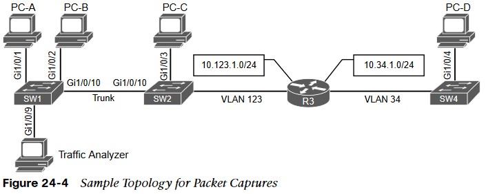
Sample Topology for Packet Captures Wireshark pcap
PC-A, PC-B, PC-C, PC-D spread across three switches and a traffic analyzer connected to SW1. PC-A, PC-B, and PC-C all connected to VLAN 123 on the 10.123.1.0/24, PC-D connected to VLAN 34, which is on the 10.34.1.0/24.
Local SPAN
The most basic form of packet capture as all the configuration occurs on a single switch. The destination of the mirrored traffic can be one or more local ports. The source of the capture can be: • One or more specific switch ports
- A port channel (EtherChannel)
- A VLAN
Also consider the following:
- Most switches support at least two SPAN sessions, but newer hardware can support more than two.
- The source port cannot be reused between two different SPAN sessions.
- Source ports can be switched or routed ports.
- The destination cannot be reused between two different SPAN sessions.
- It is possible to saturate the destination port if the source ports are receiving more data than the destination port can transmit.
Specifying the Source Ports
- monitor session session-id source {interface interface-id | vlan vlan-id} [rx | tx | both].
- The SPAN session-id allows for the switch to correlate the source ports to specific destination ports.
- The direction of the traffic can be specified as part of the configuration. With the optional rx keyword you capture only traffic received on that source, with the optional tx key word you capture traffic sent by that source, and with the both keyword you capture all traffic.
- You can specify a trunk port as a source port to capture traffic for all VLANs that traverse that port. This might provide too much data and add noise to the traffic analysis tool.
- The VLANs filtered on the capture with the command monitor session session-id filter vlan vlan-range.
Specifying the Destination Ports
- The destination port is specified with the global configuration command:
- monitor session session-id destination interface interface-id [encapsulation {dot1q [ingress {dot1q vlan vlan-id | untagged vlan vlan-id | vlan vlan-id} | replicate [ingress {dot1q vlan vlan-id | untagged vlan vlan-id]}} | ingress]
- As you can see, there are a lot of different nested options.
- A SPAN session normally copies the packets without including any 802.1Q VLAN tags or L2 protocols.
- Using the encapsulation replicate keywords includes that information. The full global configuration command is: monitor session session-id destination interface interface-id [encapsulation replicate]
Specifying the Destination Ports
- If the traffic analyzer is a Windows PC and is accessed using RDP, the port must be able to send and receive traffic for the Windows PC in addition to the traffic from the SPAN session. Situations like this require the following global configuration command:
- monitor session session-id destination interface interface-id ingress {dot1q vlan vlan-id | untagged vlan vlan-id}
- Selecting the dot1q keyword requires the packets to be encapsulated with the specified VLAN ID. Selecting the untagged keyword accepts incoming packets and associates them to the specified VLAN ID.
- STP is disabled on the destination port to prevent extra BPDUs from being included in the network analysis.
- Great care should be taken to prevent a forwarding loop on this port.
Local SPAN Configuration Examples
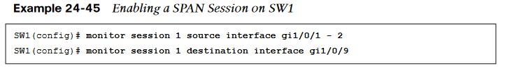
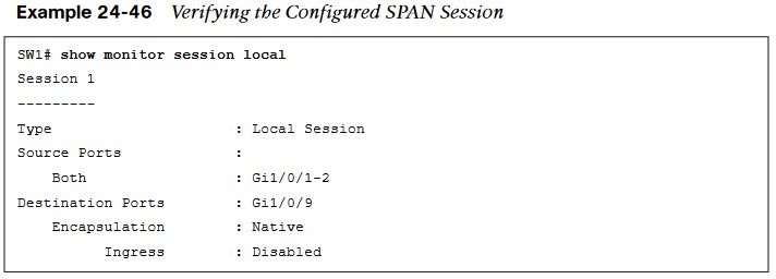
Local SPAN Configuration Examples
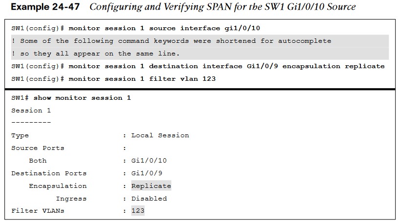
- The next example illustrates monitoring the trunk port Gi1/0/10 and provides the output to PC-B for PC-A and PC-B communication on SW1 and sending it toward the local traffic analyzer.
Local SPAN Configuration Examples

- In the last scenario, the switch is configured to monitor PC-A’s traffic, and it uses an already installed network traffic analysis tool on PC-B.
- When the switch is configured, PCB can be accessed remotely to view the network traffic by using RDP.
- Example 24-48 lists the commands that are entered on SW1 to capture the ingress traffic and shows the configuration being verified.
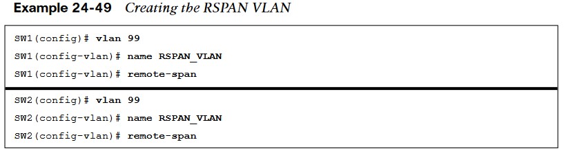
Remote SPAN (RSPAN)
- In large environments, it might be not be possible to move a network analyzer to other parts of the network. RSPAN VLAN being created on SW1 and SW2.
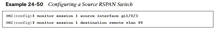
- The configuration of RSPAN on the source switch, SW2. Traffic from PC-C is sent to SW1 for analysis.
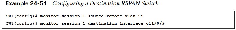
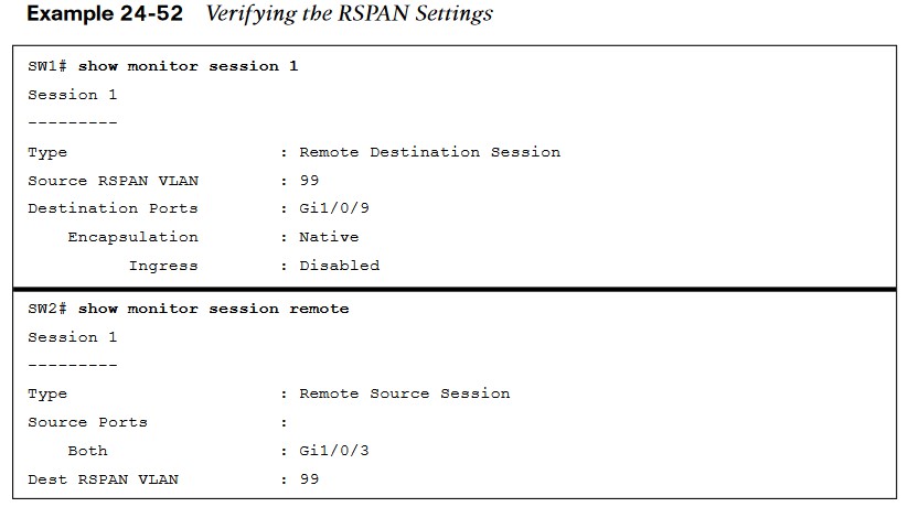
Configuration of RSPAN on the Destination Switch
- The configuration of RSPAN on the destination switch, SW1. The traffic is sent to the traffic analyzer for analysis.
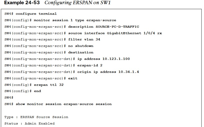
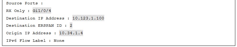
Encapsulated Remote SPAN (ERSPAN)
In large environments, it might not be possible to move a network analyzer to other parts of the network. ERSPAN provides the ability to monitor traffic in one area of the network and route the SPAN traffic to a traffic analyzer in another area of the network through Layer 3 routing.
Specifying the Source Ports
- A source and destination must be configured. To configure a source, the following command is issued:
- monitor session span-session-number type erspan-source. This defines the session number as well as the session type, erspan-source.
- Once the initial session is created, the source must be defined in the session. This is accomplished by issuing the source { interface type number | vlan vlan-ID } [ , | – | both | rx | tx ] command.
Encapsulated Remote SPAN (ERSPAN) (Cont.)
- When the source configured, it is necessary to configure the destination of the ERSPAN session.
- To enter the destination subconfiguration mode, the destination command used.
- The rest of the commands will be issued in the destination subconfiguration mode to specify the destination of the ERSPAN session as well as any parameters associated with the configuration of the destination.
- The next step is to identify the IP address of the destination for the ERSPAN session. Because this is a Layer 3 SPAN session, this IP address is where the traffic will be sent to be analyzed. The command to configure this action is simply ip address ip-address.
- The final step is to assign a ToS or TTL to the ERSPAN traffic. This is done with the erspan { tos tos-value | ttl ttl-value } command from global configuration mode.
ERSPAN Process