About Lesson
Rapid Spanning Tree Protocol
the improvements made to STP for faster convergence.
- IEEE 802.1D has only one topology tree and a slower convergence which can be problematic.
- RSTP IEEE 802.1W reduces the number of port states to be faster and more efficient.
Rapid Spanning Tree Port States
Larger environments with multiple VLANs need different STP topologies for traffic engineering purposes.
- Cisco created the proprietary Per-VLAN Spanning Tree (PVST) and Per-VLAN Spanning Tree Plus (PVST+)
- RSTP IEEE 802.1W reduces the number of port states to three:
| Port States | Description |
| Discarding | The switch port is enabled, but the port is not forwarding any trafficto ensure that a loop is not created. |
| Learning | The switch port modifies the MAC address table. The switch still doesnot forward any other network traffic besides BPDUs. |
| Forwarding | The switch port forwards all network traffic and updates the MACaddress table as expected. |
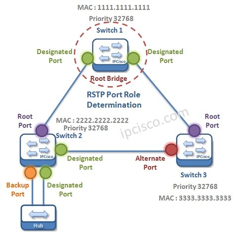
Rapid Spanning Tree Port Roles
RSTP defines the following port roles:
| Port Roles | Description |
| Root port(RP): | A port that connects to the root bridge or an upstream switch. Thereshould be only one root port per VLAN. |
| Designated port (DP): | A port that receives and forwards BPDU frames to other switches.Designated ports provide connectivity to downstream devices andswitches. There should be only one active designated port on a link. |
| Alternateport: | A port that provides alternate connectivity toward the rootswitch through a different switch. |
| Backup port: | A port that provides link redundancy toward the current rootswitch. A backup port exists only when multiple links connectbetween the same switches. |
Rapid Spanning Tree Port Types
RSTP defines three types of ports that are used for building the STP topology:
| Port Roles | Description |
| Edge Port | A port at the edge of the network where hosts connect to and cannotform a loop. These ports have the STP portfast feature enabled. |
| Root port | A port that has the best path cost toward the root bridge. There canbe only one root port on a switch. |
| Point-to-Point port | Any port that connects to another RSTP switch with full duplex. Full-duplex links do not permit more than two devices on a networksegment, so determining whether a link is full duplex is the fastestway to check the feasibility of being connected to a switch. |
Multi-access connections (Hubs) must use 802.1D.
Building the Rapid Spanning Tree Protocol Topology
RSTP switches exchange handshakes with other RSTP switches to transition through the following STP states faster. They establish a bidirectional handshake across the shared link to identify the root bridge. The process proceeds as follows:
- As the first two switches connect to each other, they verify that they are connected with a point-to-point link by checking the full-duplex status.
- They establish a handshake with each other to advertise a proposal (in configuration BPDUs) that their interface should be the DP for that port.
- There can be only one DP per segment, so each switch identifies whether it is the superior or inferior switch, using the same logic as in 802.1D for the system identifier (that is, the lowest priority and then the lowest MAC).
Building the RSTP Topology
- The inferior switch (SW2) recognizes that it is inferior and marks its local port (Gi1/0/1) as the RP. At that same time, it moves all non-edge ports to a discarding state. At this point in time, the switch has stopped all local switching for non-edge ports.
- The inferior switch (SW2) sends an agreement (configuration BPDU) to the root bridge (SW1), which signifies to the root bridge that synchronization occurring on that switch.
- The inferior switch (SW2) moves its RP (Gi1/0/1) to a forwarding state. The superior switch moves its DP (Gi1/0/2) to a forwarding state, too.
- The inferior switch (SW2) repeats the process for any downstream switches connected to it.
Other useful information:
Join the conversation