About Lesson
OSPF Configuration
the OSPF configuration techniques and commands that can be executed to verify the exchange of routes.
The command router ospf process-id defines and initializes the OSPF process. OSPF is enabled on an interface using two methods:
- An OSPF network statement
- Interface-specific configuration
OSPF Network Statement
- The OSPF network statement identifies the interfaces that the OSPF process will use and the area that those interfaces participate in. The network statements match against the primary IPv4 address and netmask associated with an interface.
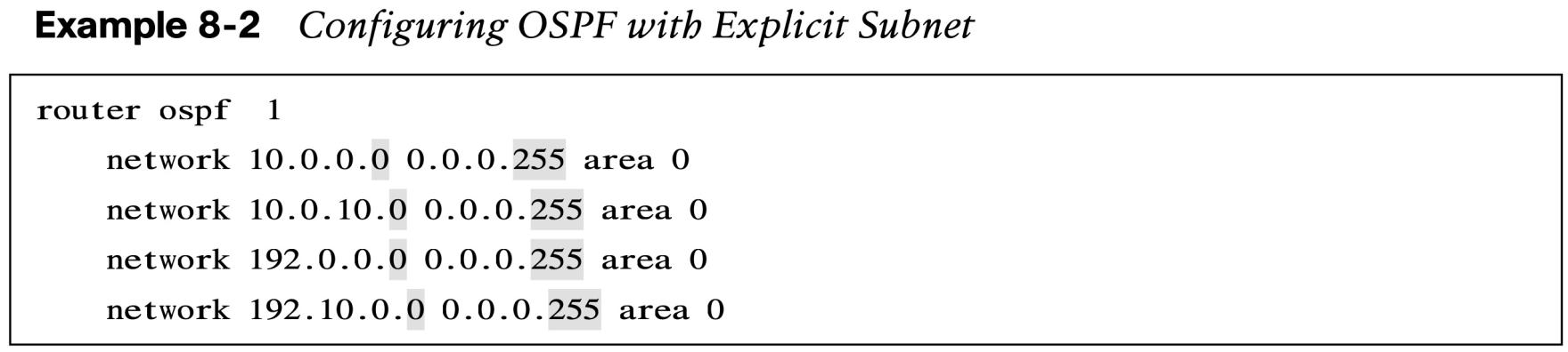
- The selection of interfaces within the OSPF process is accomplished by using the command network ip-address wildcard-mask area area-id. This is similar to configuring EIGRP, except that the OSPF area is specified. Example 8-2 provides one method.
- The connected network for the OSPF-enabled interface is added to the OSPF LSDB under the corresponding OSPF area in which the interface participates.
Interface-Specific Configuration
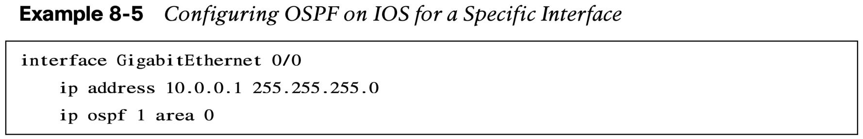
- The second method for enabling OSPF on an interface for IOS is to configure it specifically on an interface with ip ospf process-id area area-id. This configuration is not centralized and increases in complexity as the number of interfaces on the routers increases. If a hybrid configuration exists on a router, interface-specific settings take precedence over the network statement with the assignment of the areas.
Statically Set the RID and Passive Interfaces
- The OSPF topology is built on the RID. Setting a static RID helps with troubleshooting and reduces LSAs when a RID changes in an OSPF environment.
- The command router-id router-id statically assigns the OSPF RID under the OSPF process.
- The command clear ip ospf process restarts the OSPF process on a router so that OSPF can use the new RID.
- Making a network interface passive still adds the network segment into the LSDB but prohibits the interface from forming OSPF adjacencies. A passive interface does not send out OSPF hellos and does not process any received OSPF packets. The command passive interface-id under the OSPF process makes the interface passive, and the command passive interface default makes all interfaces passive. To allow for an interface to process OSPF packets, the command no passive interface-id is used.
Requirements for Neighbor Adjacency
The following list of requirements must be met for an OSPF neighborship to be formed:
- RIDs must be unique between the two devices.
- The interfaces must share a common subnet.
- The MTUs on the interfaces must match.
- The area ID must match for the segment.
- The DR enablement must match for the segment.
- OSPF hello and dead timers must match for the segment.
- Authentication type and credentials (if any) must match for the segment.
- Area type flags must match for the segment (for example, Stub, NSSA).
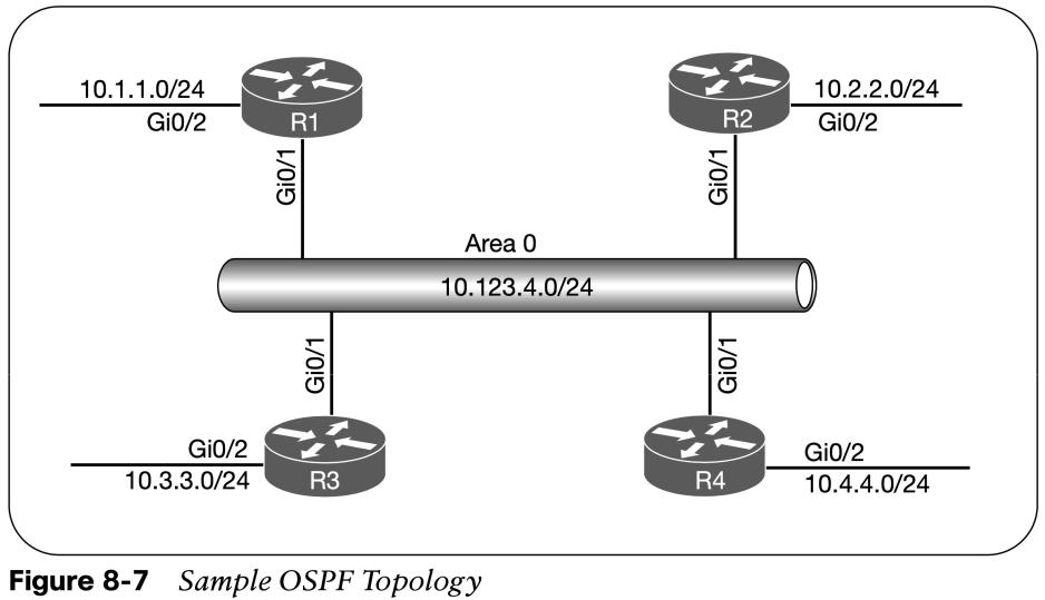
Sample Topology and Interface Confirmation
- Figure 8-7 shows a topology of a basic OSPF configuration. All routers have loopback IP addresses matching their RIDs. On R1 and R2, OSPF is enabled on all interfaces, R3 uses specific network-based statements, R4 uses interface-specific commands. R1 and R2 set Gi0/2 interface as passive, and R3 and R4 make all interfaces passive by default but make Gi0/1 active.
- Verify that the correct interfaces are running OSPF after making changes to the OSPF configuration. The command show ip ospf interface [brief | interface-id] displays the OSPF-enabled interfaces.
OSPF Interface Columns
| Field | Description |
| Interface | Interfaces with OSPF enabled |
| PID | The OSPF process ID associated with this interface |
| Area | The area that this interface is associated with |
| IP Address/Mask | The IP address and subnet mask for the interface |
| Cost | The cost metric assigned to an interface that is used to calculate a path metric |
| State | The current interface state, which could be DR, BDR, DROTHER, LOOP, or Down |
| Nbrs F | The number of neighbor OSPF routers for a segment that are fully adjacent |
| Nbrs C | The number of detected neighbor OSPF routers for a segment in a 2-Way state |
Verification of OSPF Neighbor Adjacencies
| Field | Description |
| Neighbor ID | The router ID (RID) of the neighboring router. |
| PRI | The priority for the neighbor’s interface, which is used for DR/BDR elections. |
| State | The first field is the neighbor state. The second field is the DR, BDR, or DROTHER role if |
| the interface requires a DR. | |
| Dead Time | The time left until the router is declared unreachable. |
| Address | The primary IP address for the OSPF neighbor. |
| Interface | The local interface to which the OSPF neighbor is attached. |
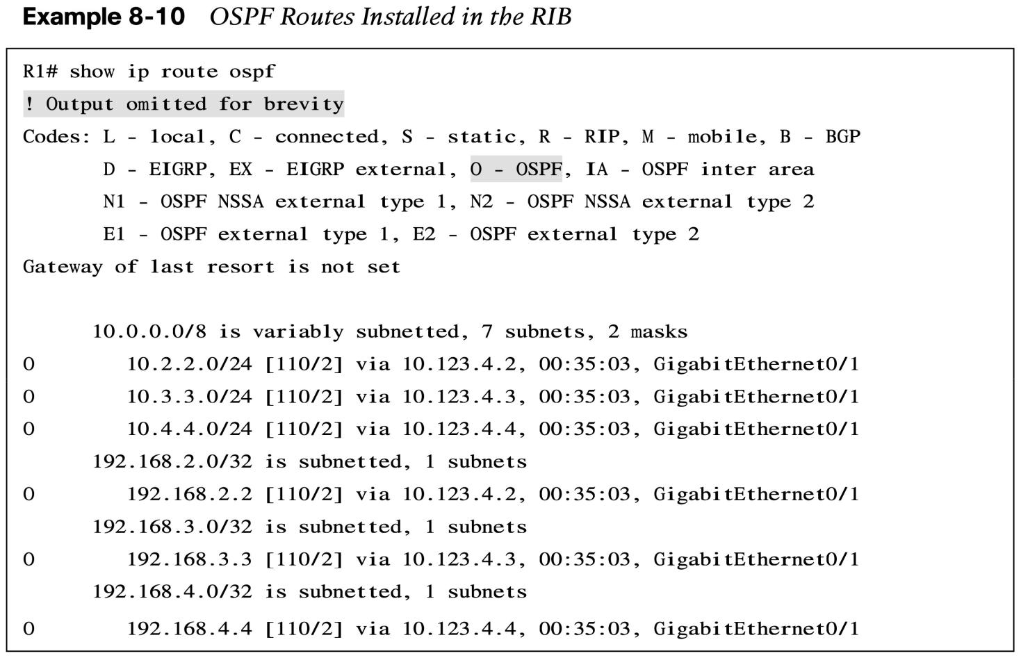
Verification of OSPF Routes
 Other useful information:
- Full ENCOR Course
- CCNP Enterprise Certificate Information
- 350-401 ENCOR Exam Questions and Solutions
- 350-401 ENCOR Exam Topics
Join the conversation