Network Device Communication
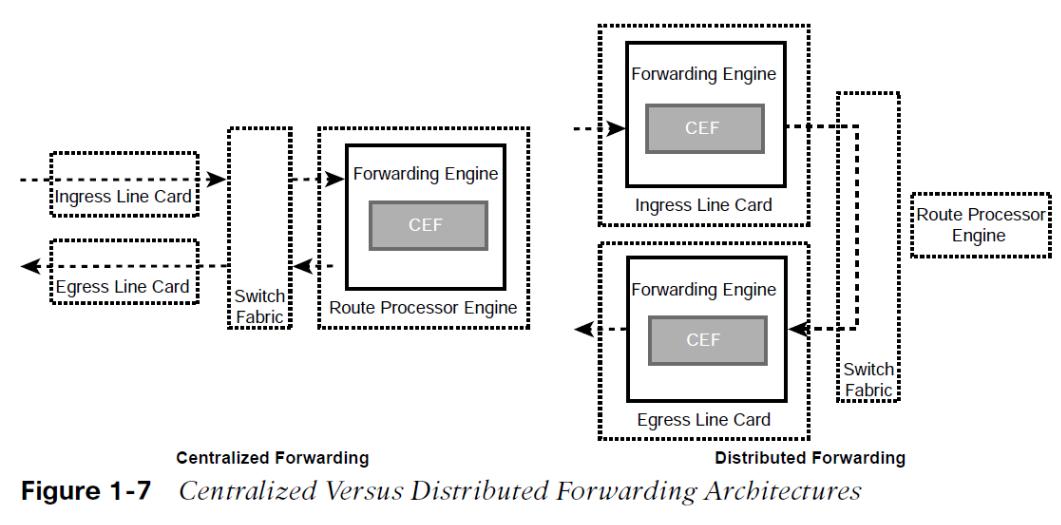
how switches forward traffic from a L2 perspective and routers forward traffic from a L3 perspective.
- The primary function of a network is to provide connectivity between devices.
- Today almost everything based on TCP/IP.
OSI Model

L2 Forwarding and Collision Domains
The data link layer handles addressing beneath the IP protocol stack so that communication is directed between hosts. Ethernet commonly uses media access control addresses (MAC).
- Ethernet devices use Carrier Sense multiple Access/Collision Detect (CSMA/CD) to ensure that only one device talks at a time in a collision domain.
- Devices can only transmit or receive data at one time (half-duplex).
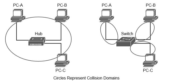
Collision Domains on a Hub Versus a Switch
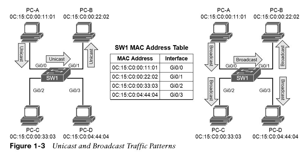
- Unknown unicast flooding occurs when a packet contains a destination MAC not in CAM table.
- The switch forwards the packet out of every switch port.
- Broadcast traffic is network traffic intended for every host and forwarded out of every switch port.
- Network broadcasts do not cross L3 boundaries.
VLANs
Adding a router between LAN segments helps shrink broadcast domains. VLANS provide logical segmentation by creating multiple broadcast domains on the same switch. VLANS defined in the IEEE 802.1Q standard, which states that the 32 bits are added to the packet header with the following fields: tag Protocol identifier (TPID), priority code point (PCP), drop eligible indicator (DEI), VLAN ID. 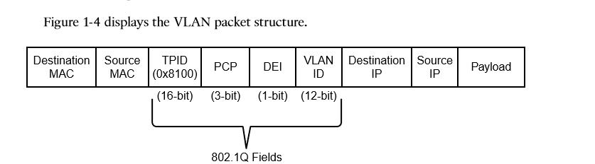
Creating a VLAN
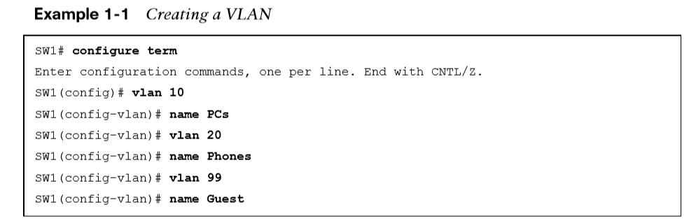
VLANs and their port assignment are verified with show vlan [{brief | id vlan-id | name vlanname | summary}].
Optional show vlan keywords
Optional show vlan keywords:
- Brief – Displays only the relevant port-to-VLAN mappings.
- Summary – Displays a count of VLANs, VLANs participating in VTP, and VLANs that in the extended VLAN range.
- id vlan-id – Displays all the output from the original command but filtered to only the VLAN number specified.
- name vlanname – Displays all the output from the original command but filtered to only the VLAN name specified.
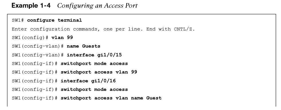
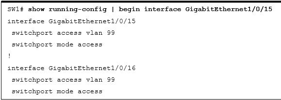
Access Ports
- Assigned to only one VLAN.
- It carries traffic from the specified VLAN to the device connected to it or from the device to other devices on the same VLAN.
- Catalyst switch ports are L2 by default.
- Use #switchport mode access to manually configure a port as an access port.
- A specific VLAN is associated to the port with switchport access {vlan vlan-id | name vlanname}.
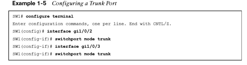
Trunk Ports
- Carry multiple VLANs.
- Typically used when multiple VLANs need connectivity between a switch and another switch, router, or firewall and use only one port.
- Statically defined on switches with #switch-port mode trunk.
Trunk Ports
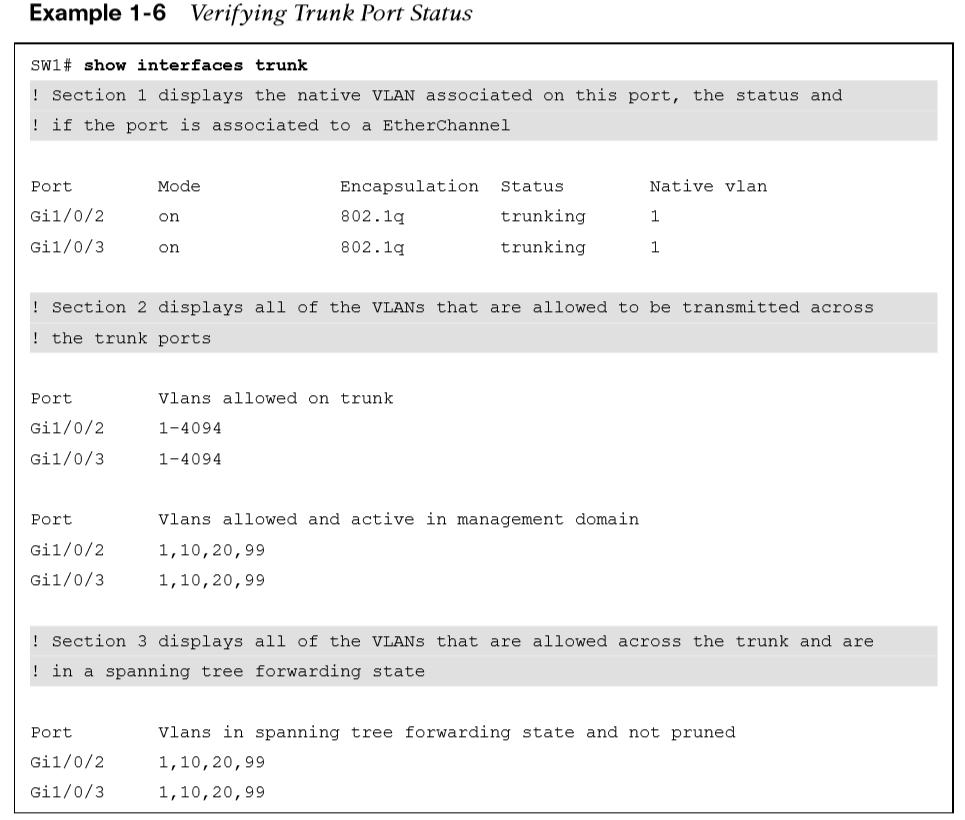
#show interfaces trunk provides:
- The first section lists all the trunk ports, the status, the association to an EtherChannel, and native VLAN.
- The second displays the list of VLANs that are allowed on the trunk port. Traffic can be minimized on trunk ports to restrict VLANs to specific switches, thereby restricting broadcast traffic, too.
- The third displays the VLANs that are in a forwarding state on the switch. Ports that are in blocking state are not listed.
Native VLANs
In the 802.1Q standard, any traffic that is advertised or received on a trunk port without the 802.1Q VLAN tag is associated to the native VLAN.
- The default native VLAN is VLAN 1.
- When a switch has two access ports configured as access ports and associated to VLAN 10—that is, a host attached to a trunk port with a native VLAN set to 10—the host could talk to the devices connected to the access ports.
- The native VLAN should match on both trunk ports, or traffic can change VLANs unintentionally. While connectivity between hosts is feasible (assuming that they are on the different VLAN numbers), this causes confusion for most network engineers and is not a best practice.
- A native VLAN is a port-specific configuration and is changed with the interface command switchport trunk native vlan vlan-id.
Allowed VLANs
#switchport trunk allowed vlan vlan-ids specifies the VLANs that are allowed to traverse the link. 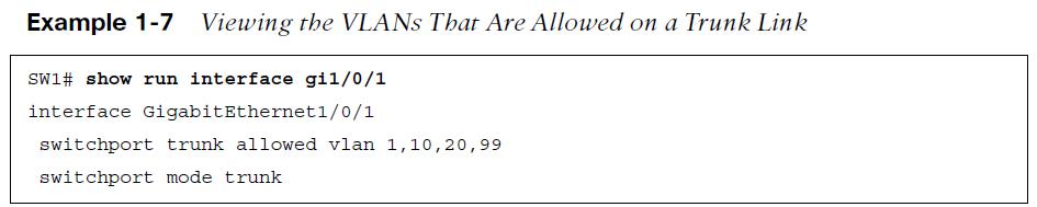
- switchport trunk allowed {vlan-ids | all | none | add vlan-ids | remove vlan-ids | except vlan-ids} provides a lot of power in a single command.
- The optional keyword all allows for all VLANs, while none removes all VLANs from the trunk link.
- The add keyword adds additional VLANs to those already listed, and the remove keyword removes the specified VLAN from the VLANs already identified for that trunk link.
MAC Address Table
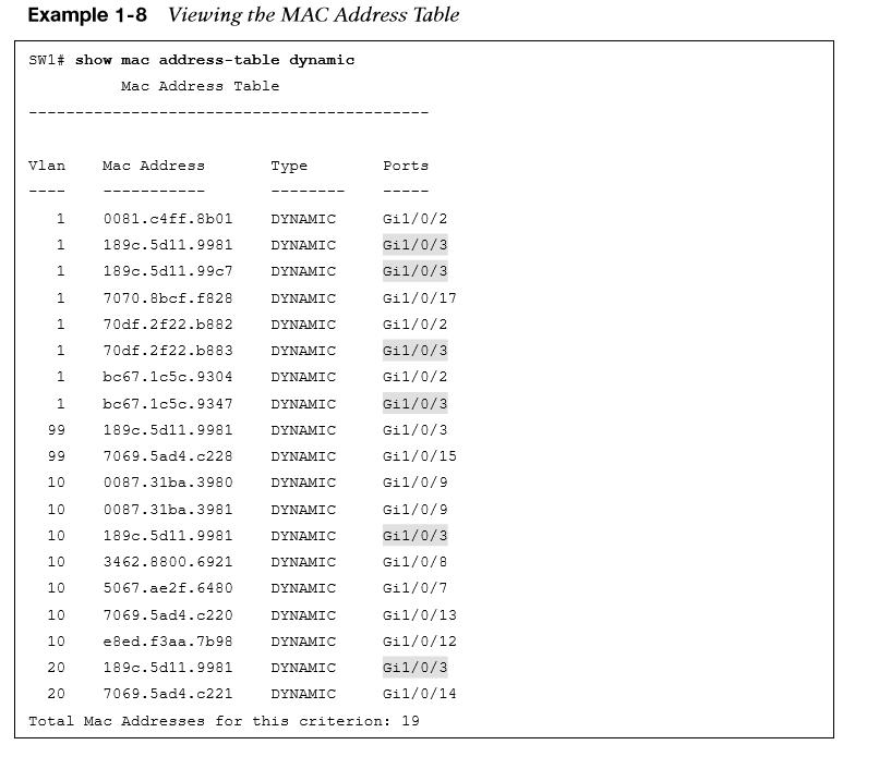
The MAC table is responsible for identifying the switch ports and VLANs with which a device is associated. A switch builds the MAC table by examining the source MAC for the traffic that it receives. This information is then maintained to shrink the collision domain (point-to-point communication between devices and switches) by reducing the amount of unknown unicast flooding.
MAC Table
Displayed with show mac address-table [address mac-address | dynamic | vlan vlan-id]. The optional keywords with this command provide the following benefits:
- address mac-address – Displays entries that match the explicit MAC. This command could be beneficial on switches with hundreds of ports.
- dynamic – Displays entries that are dynamically learned.
- vlan vlan-id – Displays entries that matches the specified VLAN.
MAC Address Table
- mac address-table static mac-address vlan vlan-id {drop | interface interface-id} adds a manual entry with the ability to associate it to a specific switch port or to drop traffic upon receipt.
- clear mac address-table dynamic [{address mac-address | interface interface-id | vlan vlan-id}] flushes the MAC table for the entire switch.
- The MAC table resides in content addressable memory (CAM). The CAM uses high-speed memory that is faster than typical RAM due to its search techniques. The CAM table provides a binary result for any query of 0 for true or 1 for false.
Switch Port Status
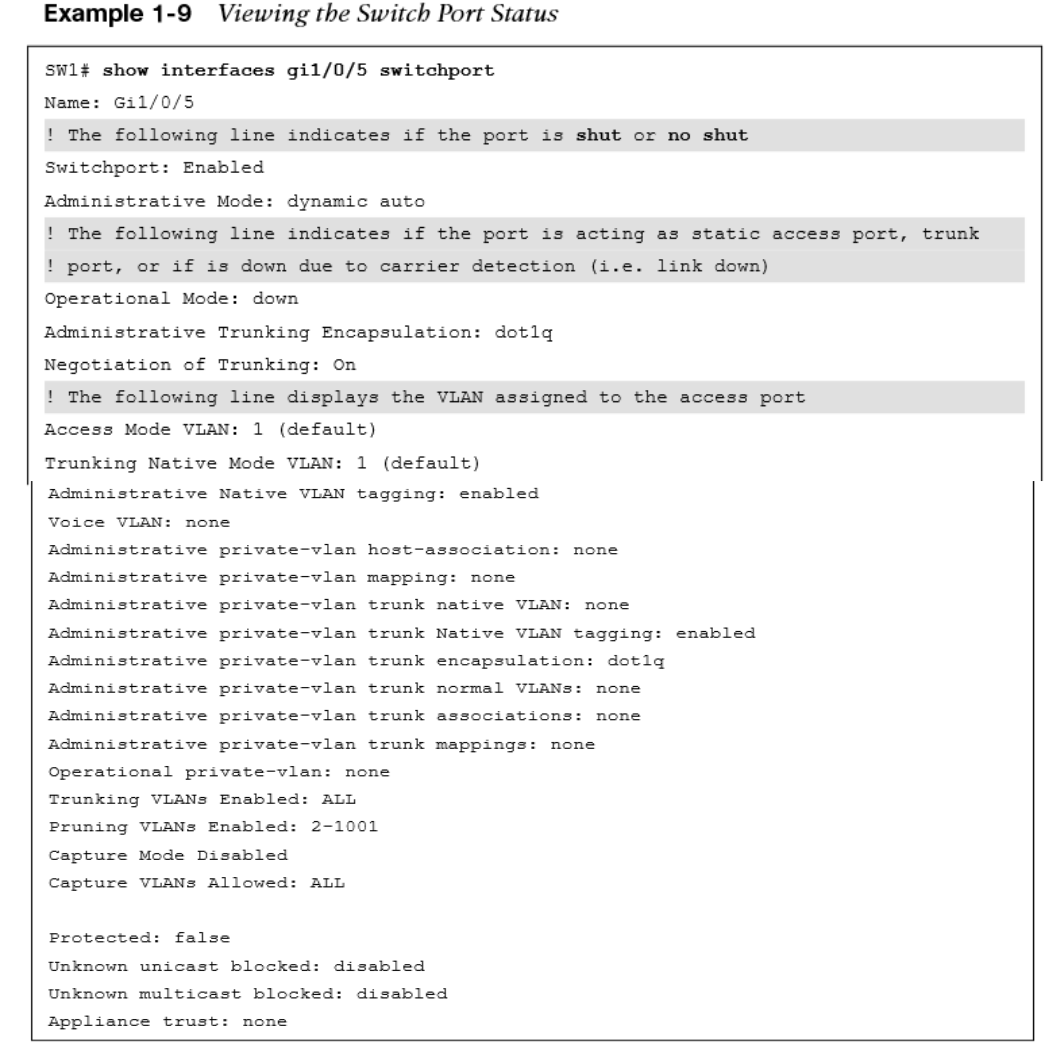
Examining the configuration for a switch port can be useful; however, some commands stored elsewhere in the configuration preempt the configuration set on the interface. show interfaces interface-id switchport provides all the relevant information for a switch port’s status. show interfaces switchport displays the same information for all ports on the switch.
Interface Status

- Port – Displays the interface ID or port channel.
- Name – Displays the configured interface description.
- Status – Displays connected for links where a connection was detected and established to bring up the link. Displays not connect for when a link is not detected and err-disabled when an error has been detected and the switch has disabled the ability to forward traffic out of that port.
Interface Status
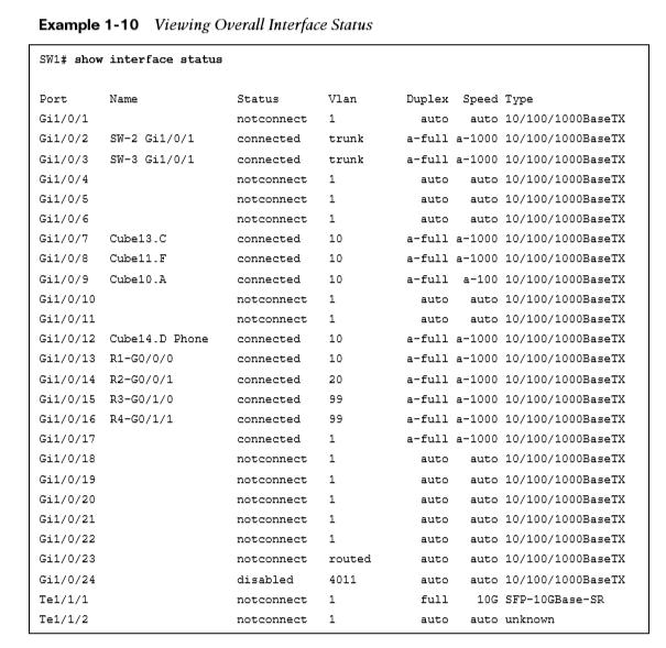
- VLAN – VLAN number assigned for access ports. Trunk links appear as trunk, and ports configured as L3 interfaces display routed.
- Duplex – the duplex of the port. If the duplex auto-negotiated, it prefixed by a-.
- Speed – the speed of the port. If the port speed was auto-negotiated, it is prefixed by a-.
- Type – Displays the type of interface for the switch port. If it is a fixed RJ-45 copper port, it includes TX in the description (for example, 10/100/1000BASE-TX). Small form-factor pluggable (SFP)–based ports are listed with the SFP model if there is a driver for it in the software; otherwise, it says unknown.
L3 Forwarding and Local Network Forwarding
Some of the L3 forwarding logic occurs before L2 forwarding. There are two main methodologies for L3 forwarding:
- Forwarding traffic to devices on the same subnet
- Forwarding traffic to devices on a different subnet
Local Network forwarding
- Two devices that reside on the same subnet communicate locally. As the data is encapsulated with its IP address, the device detects that the destination is on the same network. However, the device still needs to encapsulate the L2 info to the packet. It knows its own MAC but does not initially know the destination’s MAC.
- The ARP table provides a method of mapping L3 IP to L2 MAC addresses by storing the IP of a host and its corresponding MAC address.
- The ARP table can be viewed with #show ip arp [mac-address | ip-address | vlan vlan-id | interface-id]. The optional keywords make it possible to filter the information.
Packet Routing
Packets must be routed when two devices are on different networks. As the data is encapsulated with its IP, a device detects that its destination is on a different network and must be routed. The device checks its local routing table to identify its next-hop IP address, which may be learned in one of several ways:
- From a static route entry, it can get the destination network, subnet mask, and next-hop IP.
- A default-gateway is a simplified static default route that just asks for the local next-hop IP address for all network traffic.
- Routes can be learned from routing protocols.
- The source device must add the appropriate L2 headers (source and dest MAC), but the destination MAC is needed for the next-hop IP.
- The device looks for the next-hop IP entry in the ARP table and uses the MAC from the next-hop IP address’s entry as the destination MAC.
- The next step is to send the data packet down to Layer 2 for processing and forwarding.
- The next router receives the packet based on the destination MAC
- It analyzes the destination IP address
- Locates the appropriate network entry in its routing table
- Identifies the outbound interface
- Then finds the MAC address for the destination device (or the MAC for the next-hop address if it needs to be routed further)

Finally, the router then modifies the source MAC to the MAC address of the router’s outbound interface and modifies the destination MAC to the MAC address for the destination device (or next-hop router). 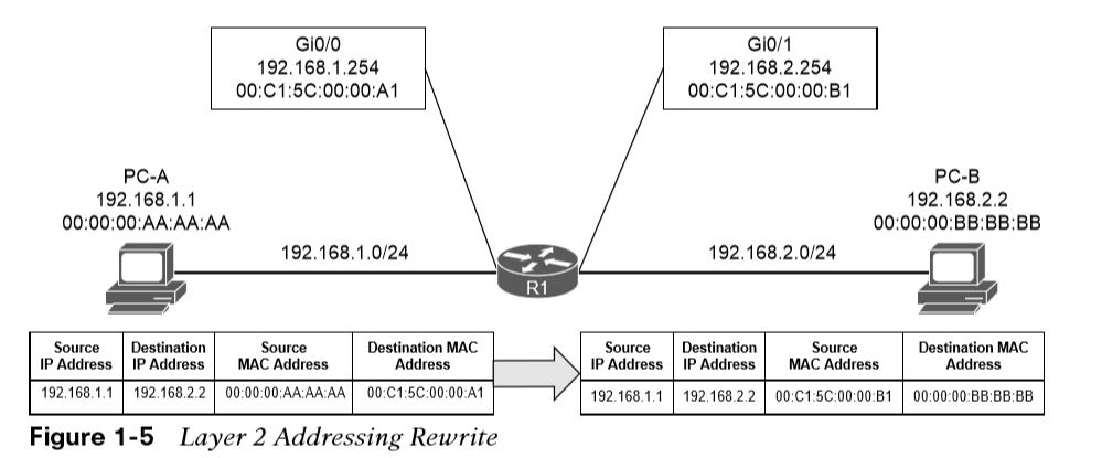
IP Address Assignment
IP address must be assigned to an interface for a router or multilayer switch to route packets. 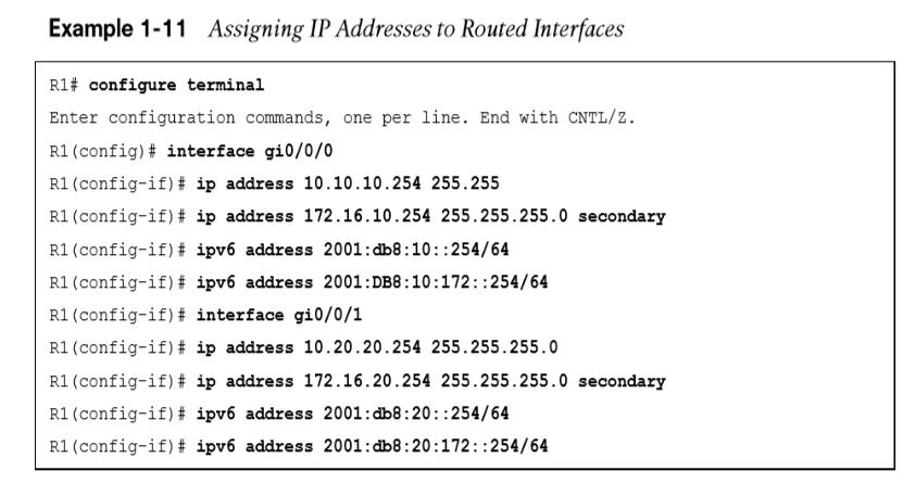
- An interface with a configured IP address and that is in an up state injects the associated network into the router’s routing table.
- Connected networks or routes have an AD 0.
- It is possible to attach multiple IPv4 networks to the same interface by attaching a secondary IPv4 address to the same interface with ip address ip-address subnet-mask secondary.
- IPv6 addresses assigned with #ipv6 address ipv6-address/prefix-length.
Routed Subinterfaces Its possible to configuring the switch’s interface as a trunk port and creating logical subinterfaces on a router. A subinterface is created by appending a period and a numeric value after the period. Then the VLAN needs to be associated with the subinterface with #encapsulation dot1q vlan-id. 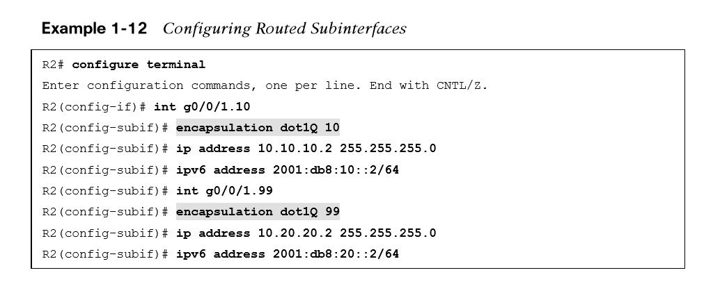
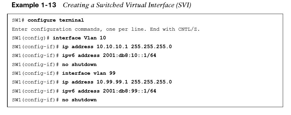
Switched Virtual Interfaces
- With Catalyst switches it is possible to assign an IP to a VLAN interface SVI.
- An SVI is configured by defining the VLAN on the switch and then defining the VLAN interface with interface vlan vlan-id.
- The switch must have an interface associated to that VLAN in an up state for the SVI to be in an up state. If the switch is a multilayer switch, the SVIs can be used for routing packets between VLANs without the need of an external router.
Routed Switchports
Some network designs include a point-to-point link between switches for routing. For example, when a switch needs to connect to a router, some would build a transit VLAN (for example, VLAN 2001) , associate the port connecting to the router to VLAN 2001, and then build an SVI for VLAN 2001. There is always the potential that VLAN 2001 could exist elsewhere in the Layer 2 realm or that spanning tree could impact the topology. Instead, the multilayer switch port can be converted from a L2 switch port to a routed switch port with the interface configuration command no switchport. Then the IP address can be assigned to it. 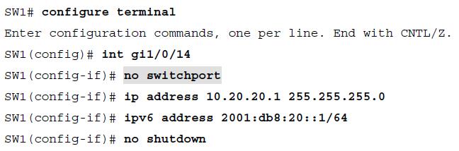
Verification of IP Addresses
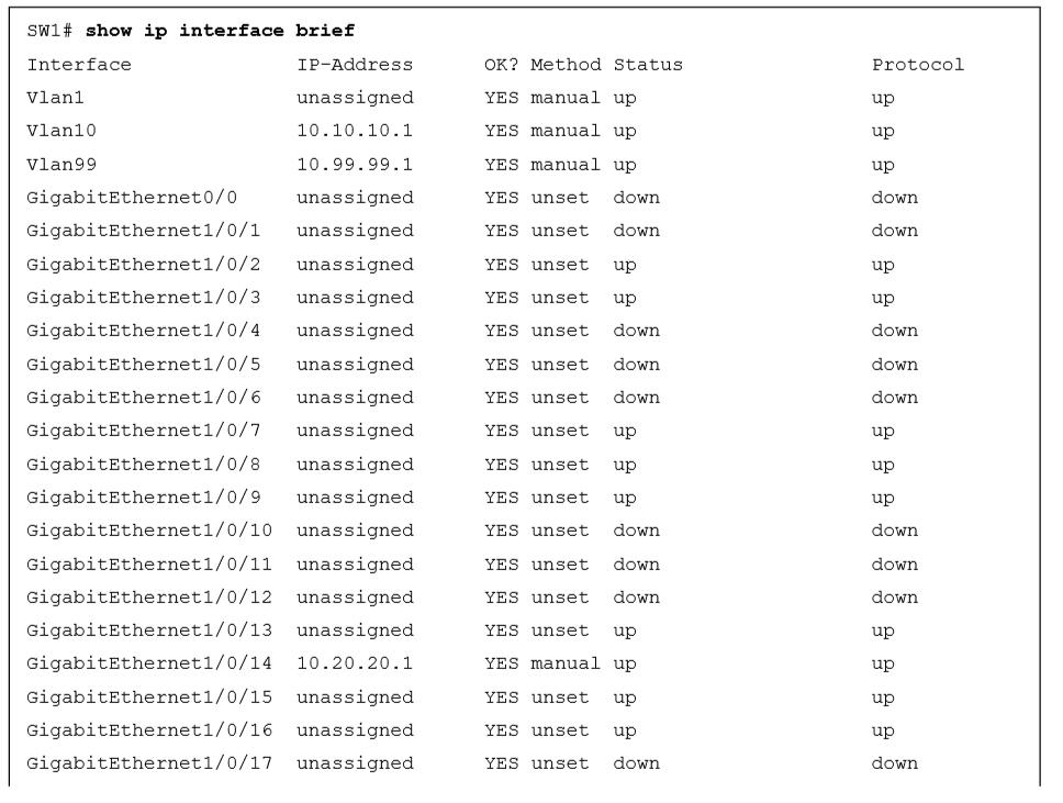
show ip interface [brief | interface-id | vlan vlan-id].
- This command’s output contains: MTU, DHCP relay, ACLs, and the primary IP address.
- The optional brief keyword displays the output in a condensed format.
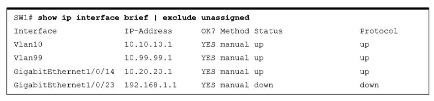
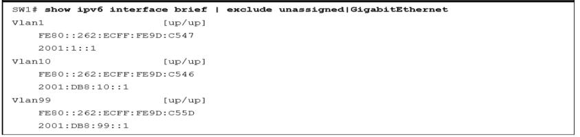
Verification of IP Addresses
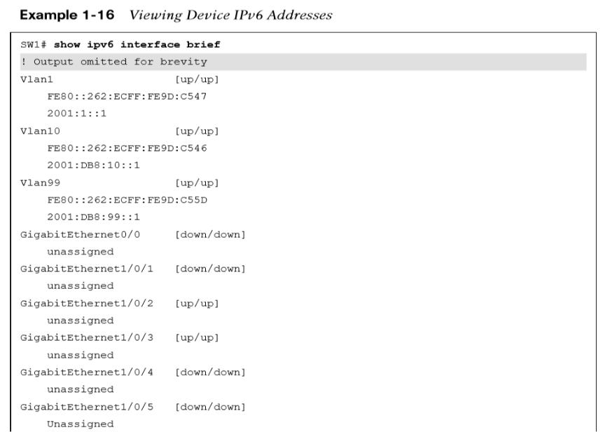
The same information can be viewed for IPv6 addresses with the command show ipv6 interface [brief | interface-id | vlan vlan-id]. Just as with IPv4 addresses, a CLI parser can be used to reduce the information to what is relevant, as demonstrated in Example 1-16.
Other useful information: