Network Address Translation
how a router can translate IP addresses from one network realm to another.
- In the early stages of the internet, large network blocks were assigned to organizations.
- Network engineers started to realize that as more people connected to the internet, the IP address space would become exhausted.
Private Network Addressing
RFC 1918 established common network blocks that are non-globally routed networks. These address blocks provide large private network blocks for companies to connect their devices together, but private IP addressing doesn’t exist on the internet. The private address blocks are as follows:
- 10.0.0.0/8 accommodates 16,777,216 hosts.
- 172.16.0.0/24 accommodates 1,048,576 hosts. 192.168.0.0/16 accommodates 65,536 hosts.
NAT enables the internal IP network to appear as a publicly routed external network. A NAT device (typically a router or firewall) modifies the source or destination IP addresses in a packet’s header as the packet is received on the outside or inside interface. NAT can be used in use cases other than just providing internet connectivity to private networks such as providing connectivity when a company buys another company, and the two companies have overlapping networks.
Network Address Translation
- NAT enables the internal IP network to appear as a publicly routed external network.
- A NAT device (typically a router or firewall) modifies the source or destination IP addresses in a packet’s header as the packet is received on the outside or inside interface.
- NAT can be used in use cases other than just providing internet connectivity to private networks, such as providing connectivity when a company buys another company, and the two companies have overlapping networks.
- Most routers and switches perform NAT translation only with the IP header addressing and do not translate IP addresses within the payload (for example, DNS requests). Some firewalls can perform NAT within the payload for certain types of traffic.
Inside/Outside Local and Global
Here are four important terms related to NAT:
- Inside local – The actual private IP address assigned to a device on the inside network(s).
- Inside global – The public IP address that represents one or more inside local IP addresses to the outside.
- Outside local – The IP address of an outside host as it appears to the inside network. The IP address does not have to be reachable by the outside but is considered private and must be reachable by the inside network.
- Outside global – The public IP address assigned to a host on the outside network. This IP address must be reachable by the outside network.
Types of NAT
Three types of NAT commonly used today are as follows:
- Static NAT – Provides a static one-to-one mapping of a local IP address to a global IP address.
- Pooled NAT – Provides a dynamic one-to-one mapping of a local IP address to a global IP address. The global IP address is temporarily assigned to a local IP address. After a certain amount of idle NAT time, the global IP address is returned to the pool.
- Port Address Translation (PAT) – Provides a dynamic many-to-one mapping of many local IP addresses to one global IP address. The NAT device translates the private IP address and port to a different global IP address and port. The port is unique from any other ports, which enables the NAT device to track the global IP address to local IP addresses based on the unique port mapping.
NAT Example
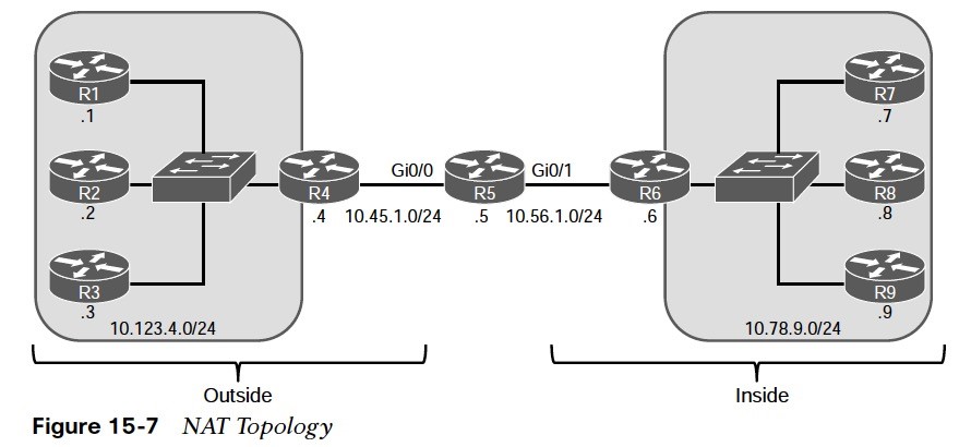
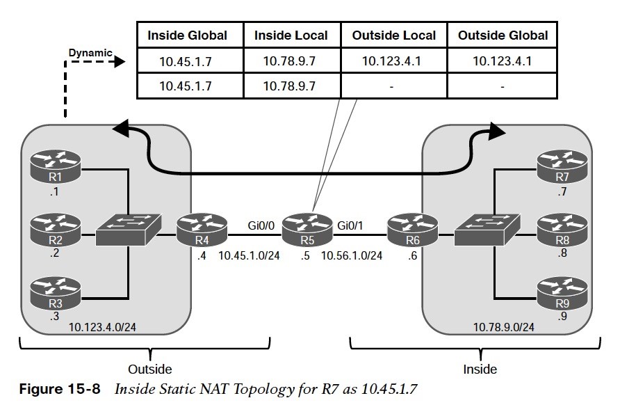
Figure 15-7 is used throughout this section to illustrate NAT. R5 performs the translation; its Gi0/0 interface (10.45.1.5) is the outside interface, and its Gi0/1 (10.56.1.5) interface is the inside interface. The other devices act as either clients or servers to demonstrate how NAT functions.
NAT Example (Cont.)
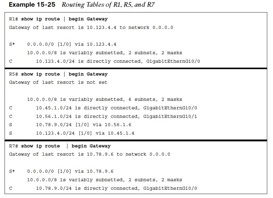
 Example 15-25 shows the routing tables of R1, R5 and R7.
- R1, R2, and R3 all have a static default route toward R4.
- R4 has a static default route to R5.
- R7, R8, and R9 all have a static default route to R6
- R6 has a static default route to R5.
- R5 has two static routes. One to the 10.123.4.0/24 network via R4 and the other to the 10.78.9.0/24 network via R6.
NAT Example (Cont.)
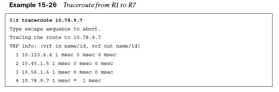
- Example 15-26 shows a traceroute from R1 to R7. The topology provides full connectivity between the outside hosts (R1, R2, and R3) and the inside hosts (R7, R8, and R9).
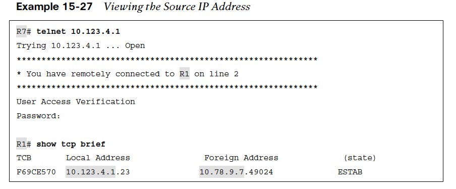
- Example 15-27 shows a telnet connection from R7 to R1. The local IP address reflects R1 (10.123.4.1) and the remote address is R7 (10.78.9.7) No NAT has occurred for this Telnet session.
Static NAT
Static NAT involves the translation of a global IP address to a local IP address, based on a static mapping of the global IP address to the local IP address. There are two types of static NAT:
- Inside static NAT – involves the mapping of an inside local (private) IP address to an inside global (public) IP address.
- Outside static NAT – involves the mapping of an outside global (public) IP address to an outside local (private) IP address.
Inside Static NAT
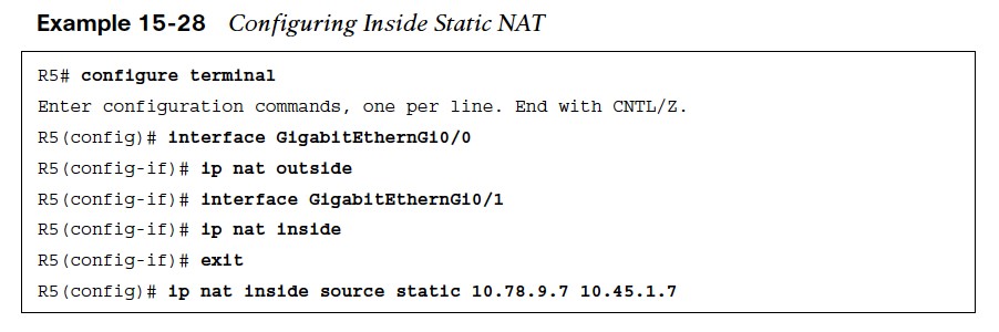
The steps for configuring inside static NAT are as follows:
- Step 1. Configure the outside interfaces by using the command ip nat outside.
- Step 2. Configure the inside interface with the command ip nat inside.
- Step 3. Configure the inside static NAT by using the command ip nat inside source static inside-local-ip inside-global-ip.
Identifying the Source with Inside Static NAT/NAT Translation Table
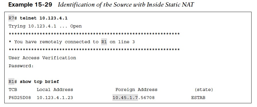 With NAT configured, a telnet session with R1 is initiated. Viewing the TCP session on R1, the local address remains 10.123.4.1 but the remote address now reflects 10.45.1.7.
 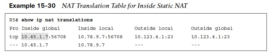 The NAT translation table consists of static and dynamic entries. The NAT translation table is displayed with the command show ip nat translations.
- The first entry is the dynamic entry correlating to the Telnet session.
- The second entry is the inside static NAT entry that was configured.
Network Address Translation (NAT) Translation Steps
The NAT translation follows these steps: 
- Step 1. As traffic enters the Gi0/1 interface on R5, R5 performs a route lookup for the destination IP address, which points out of its Gi0/0 interface. R1 is aware that the Gi0/0 interface is an outside NAT interface and that the Gi0/1 interface is an inside NAT interface and therefore checks the NAT table for an entry.
- Step 2. Only the inside static NAT entry exists, so R5 creates a dynamic inside NAT entry with the packet’s destination (10.123.4.1) for the outside local and outside global address.
NAT Translation Steps (Cont.)

- Step 3. R5 translates (that is, changes) the packet’s source IP address from 10.78.9.7 to 10.45.1.7.
- Step 4. R1 registers the session as coming from 10.45.1.7 and then transmits a return packet. The packet is forwarded to R4 using the static default route, and R4 forwards the packet using the static default route.
- Step 5. As the packet enters on the Gi0/0 interface of R5, R5 is aware that the Gi0/0 interface is an outside NAT interface and checks the NAT table for an entry.
NAT Translation Steps (Cont.)
- Step 6. R5 correlates the packet’s source and destination ports with the first NAT entry, as shown in Example 15-30, and knows to modify the packet’s destination IP address from 10.45.1.7 to 10.78.9.7.
- Step 7. R5 routes the packet out the Gi0/1 interface toward R6.
Connectivity from External Devices to the Inside Global IP Address
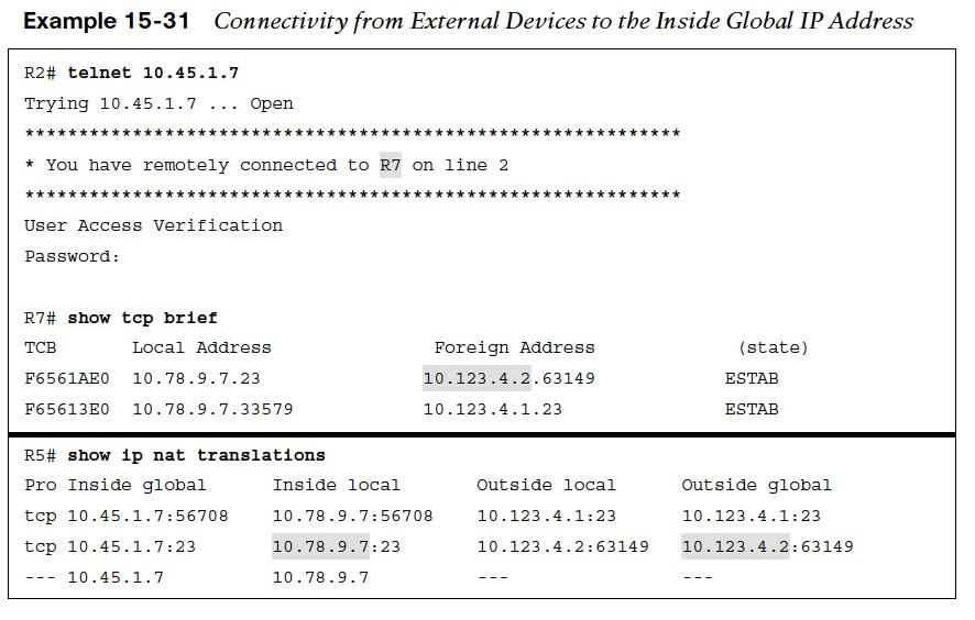 In Example 15-31:
- R2 establishes a Telnet session with R7, using the inside global IP address 10.45.1.7.
- R5 simply creates a second dynamic entry for this new session.
- From R7’s perspective, it has connected with R2 (10.123.4.2).
Outside Static Network Address Translation (NAT)
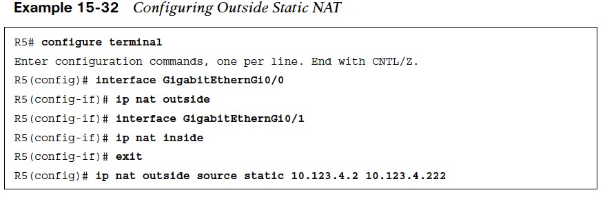
Outside static NAT involves the mapping of an outside global (public) IP address to an outside local (private) IP address. The steps for configuring outside static NAT are as follows:
- Step 1. Configure the outside interfaces by using the command ip nat outside.
- Step 2. Configure the inside interface with the command ip nat inside.
- Step 3. Configure the outside static NAT by using the command ip nat outside source static outside-global-ip outside-local-ip [add-route].
Outside Static Network Address Translation (NAT) Demonstration
R6, R7, R8, or R9 could initiate a Telnet session with R2’s IP address (10.123.4.2) and no NAT translation would occur. The same routers could initiate a Telnet session with the R2’s outside local IP address 10.123.4.222; or R2 could initiate a session with any of the inside hosts (R6, R7, R8, or R9) to demonstrate the outside static NAT entry. Example 15-33 shows R2 establishing a Telnet session with R9 (10.78.9.9). 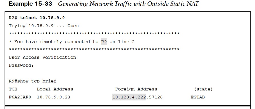
- From R9’s perspective, the connection came from 10.123.4.222.
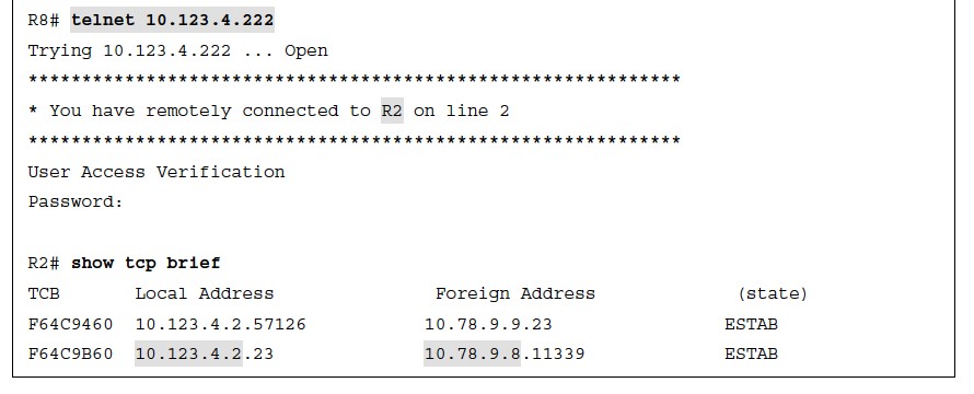
- At the same time, R8 initiated a Telnet session with the outside static NAT outside local IP address (10.123.4.222)
- From R2’s perspective, the source address is R8’s 10.78.9.8 IP address.
NAT Translation Table for Outside Static NAT
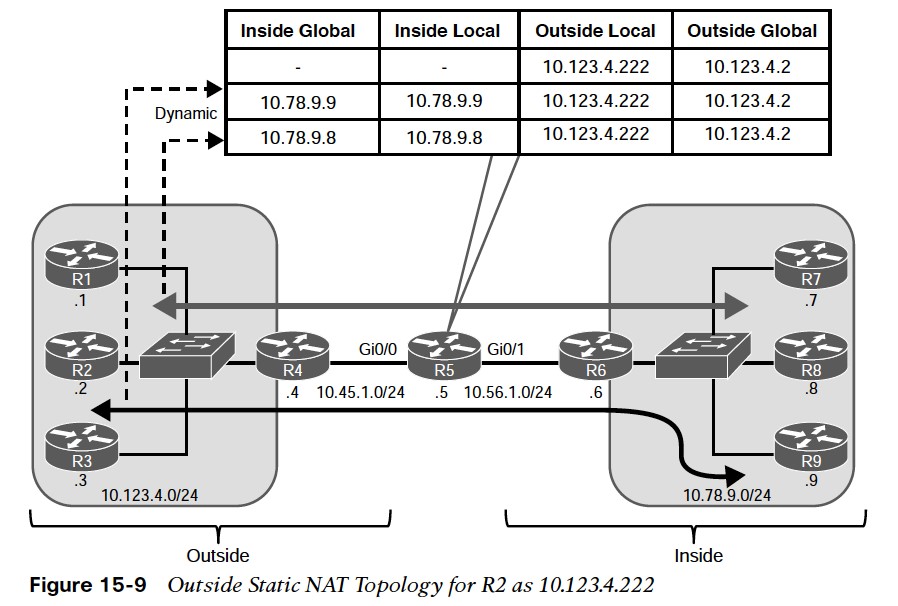 Figure 15-9 shows the translation table of R5 for the outside static NAT entry of R2 for 10.123.4.222. Example 15-34 shows the NAT translation table of R5.
 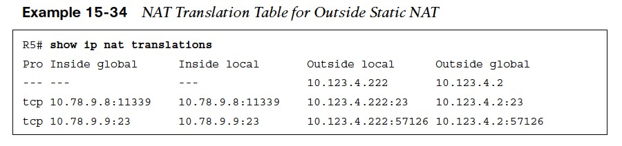 There are three entries:
- The first entry is the outside static NAT entry that was configured.
- The second entry is the Telnet session launched from R8 to the 10.123.4.222 IP address.
- The third entry is the Telnet session launched from R2 to R9’s IP address (10.78.9.9).
Pooled Network Address Translation (NAT)
- A downfall to static NAT is the number of configurations entries that must be created on the NAT device. In addition, the number of global IP addresses must match the number of local IP addresses.
- Pooled NAT provides a more dynamic method of providing a one-to-one IP address mapping—but on a dynamic, as-needed basis.
- The dynamic NAT translation stays in the translation table until traffic flow from the local address to the global address has stopped and the timeout period (24 hours by default) has expired. The unused global IP address is then returned to the pool to be used again.
- Pooled NAT can operate as inside NAT or outside NAT.
Pooled NAT Configuration Steps
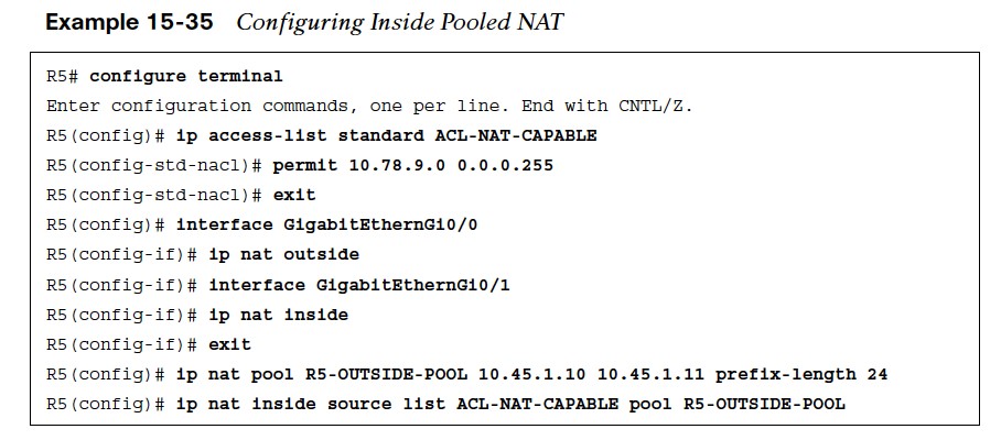
The steps for configuring inside pooled NAT are as follows:
- Step 1. Configure the outside interfaces by using the command ip nat outside.
- Step 2. Configure the inside interface with the command ip nat inside.
- Step 3. Specify which traffic to translate by using a standard or extended ACL referenced by number or name. Using a user-friendly name may be simplest from an operational support perspective
- Step 4. Define the global pool of IP addresses by using the command ip nat pool natpool-name starting-ip ending-ip prefix-length prefix-length.
- Step 5. Configure the inside pooled NAT by using the command ip nat inside source list acl pool nat-pool-name.
Configuring Inside Pooled Network Address Translation (NAT)
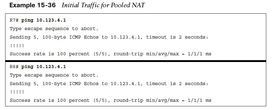
- Example 15-35 uses a NAT pool with the IP addresses 10.45.1.10 and 10.45.1.11. A named ACL, ACL-NAT-CAPABLE, allows only packets sourced from the 10.78.9.0/24 network to be eligible for pooled NAT.
- In Example 15-35, R7 and R8 ping R1 in order to generate traffic and build the dynamic inside NAT translations.
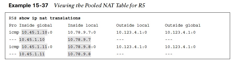
Pooled NAT Table
- In Example 15-37, there are a total of four translations in the translation table of R5. Two of them are for the full flow and specify the protocol, inside global, inside local, outside local, and outside global IP addresses.
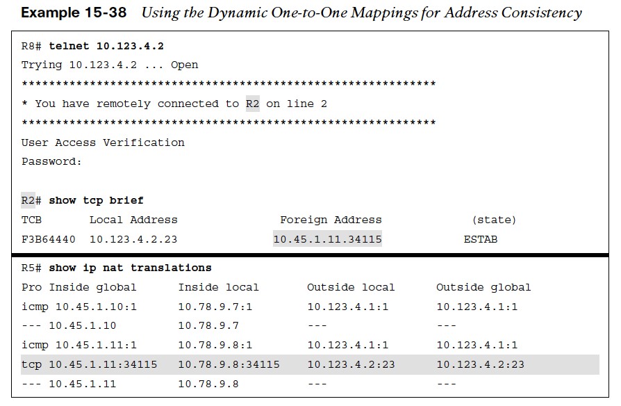
- In Example 15-38, R8 establishes a Telnet session with R2. R2 detects that the remote IP address of the session is 10.45.1.11. A second method of confirmation is to examine the NAT translation on R5, where there is a second dynamic translation entry for the full Telnet session.
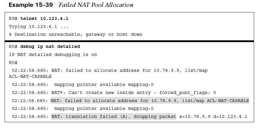
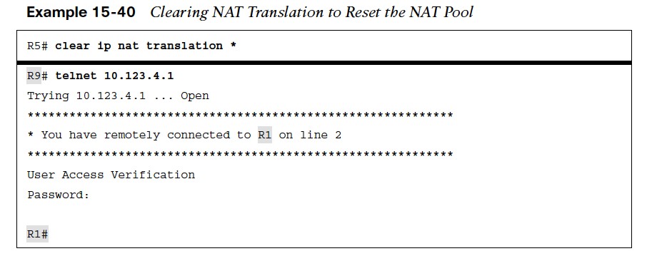
Failed NAT Pool Allocation/Reset NAT Pool
- A downfall to using pooled NAT is that when the pool exhausted, no additional translation can occur until the global IP address is returned to the pool. Example 15-39 demonstrates this concept with NAT failing on R5 and packets being dropped.
- The default timeout for NAT translations is 24 hours, but this can be changed with the command ip nat translation timeout seconds.
- The dynamic NAT translations can be cleared out with the command clear ip nat translation {ipaddress | *}, This removes all existing translations and could interrupt traffic flow on active sessions as they might be assigned new global IP addresses.
Port Address Translation
- Pooled NAT translation has the limitation of ensuring that the number of global IP addresses is adequate to meet the needs of the local IP addresses.
- Port Address Translation (PAT) is an iteration of NAT that allows for a mapping of many local IP addresses to one global IP address.
- The NAT device maintains the state of translations by dynamically changing the source ports as a packet leaves the outside interface.
- Another term for PAT is NAT overload.
Configuring PAT
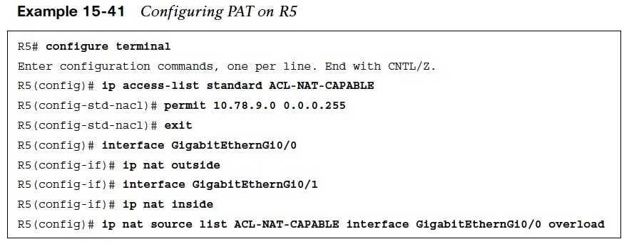 The steps for configuring PAT are as follows:
- Step 1. Configure the outside interface by using the command ip nat outside.
- Step 2. Configure the inside interface with the command ip nat inside.
- Step 3. Specify which traffic can be translated by using a standard or extended ACL referenced by number or name.
- Step 4. Configure Port Address Translation by using the command ip nat inside source list acl {interface interface-id | pool nat-poolname} overload.
Generating Traffic for PAT
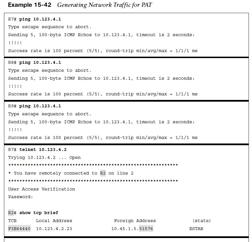
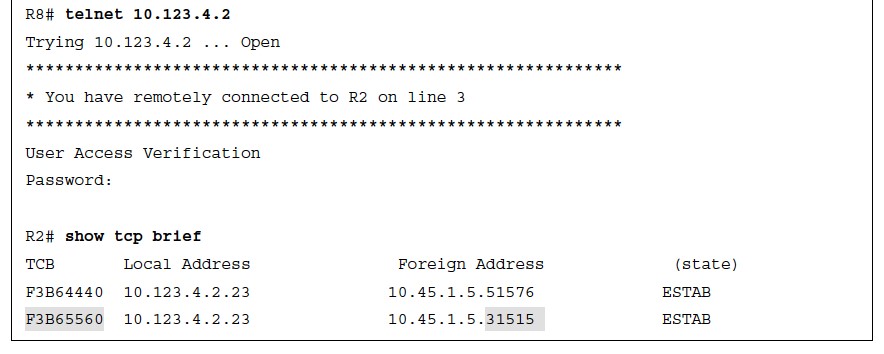 Now that PAT has been configured on R5, traffic can be generated for testing.
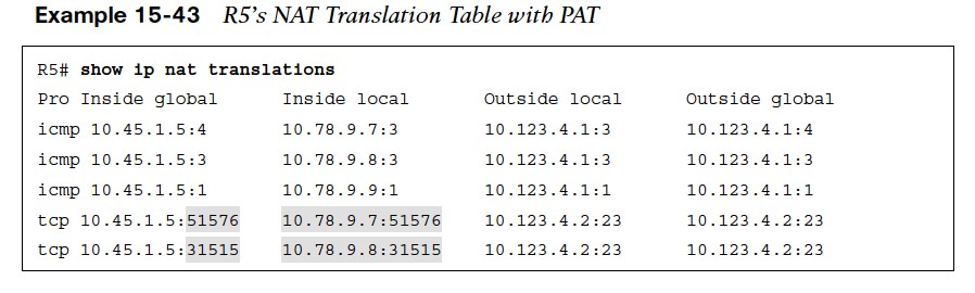
NAT Translation Table With PAT
Example 15- 43 shows R5’s NAT translation table. By taking the ports from the TCP brief sessions on R2 and correlating them to R5’s NAT translation table, you can identify which TCP session belongs to R7 or R8. 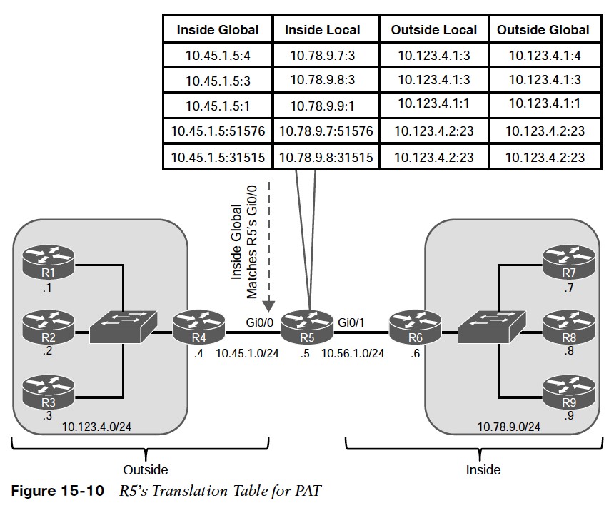
Other useful information: