Multiple Spanning Tree Protocol
the advantages and operations of Multiple Spanning Tree Protocol (MST).
- The original 802.1D standard only supported one STP instance for an entire switch network. It was not possible to load share traffic across links by blocking for specific VLANs on one line and blocking for other VLANS on alternate links.
- MST maps one or multiple VLANs to one STP instance.
CST Topology
VLANs 1 – 4 share the same topology. Traffic from SW2 to SW3 must pass through SW1. If only SW2 and SW3 had end devices in VLAN 4, the topology could not be tuned to allow traffic to traverse directly between the two switches. 
PVST Topologies
PVST provides a separate spanning tree instance for each VLAN configured on the network. The topologies below show how the switches maintain a different STP topology for each of the four VLANs. In environments with thousands of VLANs, maintaining an STP state for every VLAN can burden the switch’s processor. 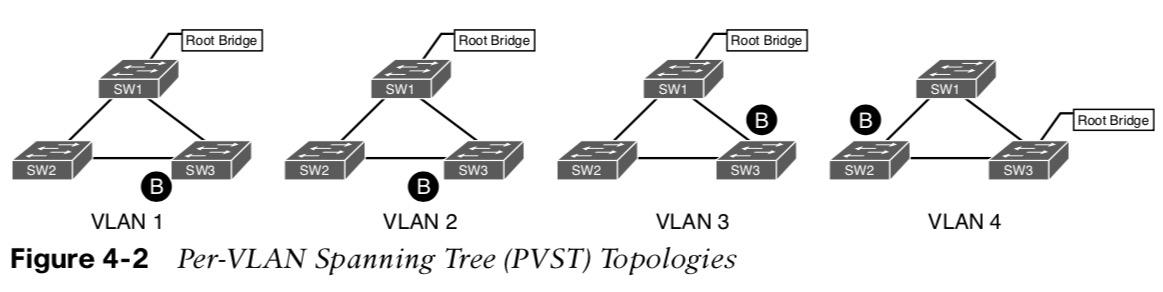
Multiple Spanning Tree (MST) Topology
MST maps one or multiple VLANs into one STP tree, called an MST instance (MSTI). 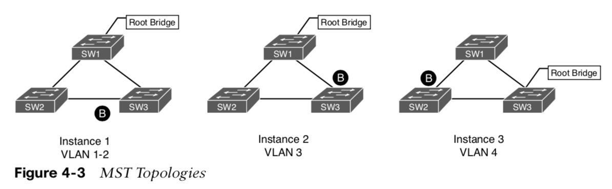 how the switches maintain STP topologies for four VLANs. If more VLANs were added to the environment, the switches would maintain three STP topologies if the VLANs aligned to one of the existing MSTIs.
Multiple Spanning Tree (MST) Region
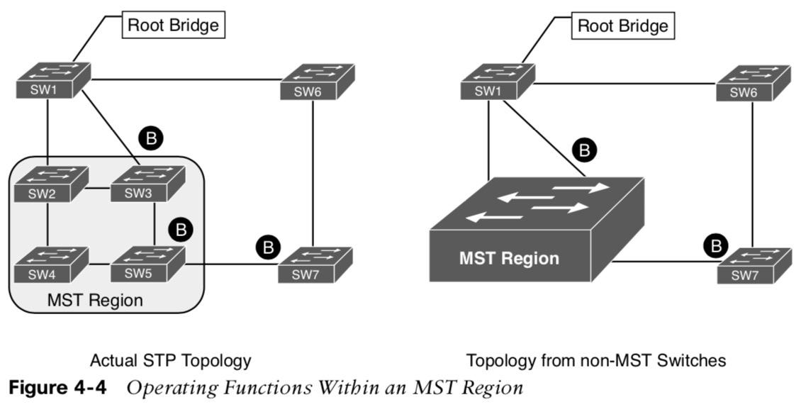
- A group of MST switches with the same high-level configuration.
- MST incorporates mechanisms that make an MST region appear as a single virtual switch to external switches.
Multiple Spanning Tree (MST) Instances
MST uses a special instance, instance 0, (IST). It is always the first instance and runs on all switch port interfaces in the MST region regardless of the VLANs associated with the ports. Additional information about other MSTIs is nested in the IST BPDU that is transmitted throughout the MST region. This allows MST to advertise only one set of BPDUs, which minimizes STP traffic.  Note: Up to 16 MST instances are supported by default.
MST Configuration
Step 1. Define MST as the spanning tree protocol with spanning-tree mode mst Step 2. (Optional) Define MST instance priority, using one of two methods:
- spanning-tree mode mst instance-number priority priority
- spanning-tree mode mst instance-number root {primary | secondary} [diameter diameter]
(Note: Priority is a value between 0 and 61,440 in increments of 4096. The primary keyword sets the priority to 24,576 and the secondary keyword sets the priority to 28,672.) Step 3. Associate VLANs to an MST instance. By default, all VLANs are associated to the MST 0 instance. The MST configuration sub-mode must be entered with the command spanning-tree mst configuration. Then the VLANs are assigned to a different MST instance with the command instance instance-number vlan vlan-id. 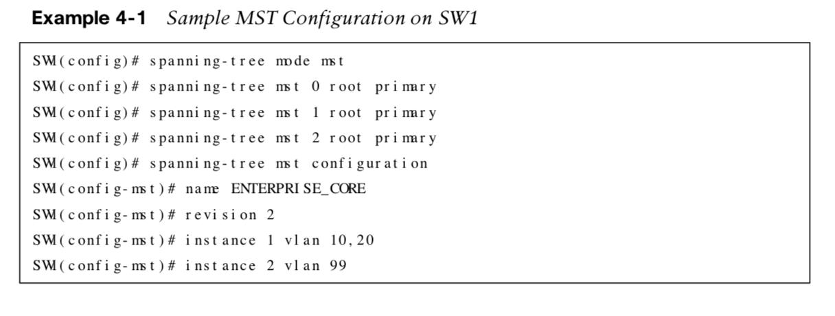 Step 4. Specify the MST version number. The MST version number must match for all switches in the same MST region. The MST version number configured with revision version. Step 5. (Optional) Define the MST region name. MST regions are recognized by switches that share a common name. By default, a region name is an empty string. The MST region name is set with name mst-region-name.
MST Verification
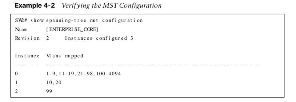
- show spanning-tree mst configuration.
- show spanning-tree.
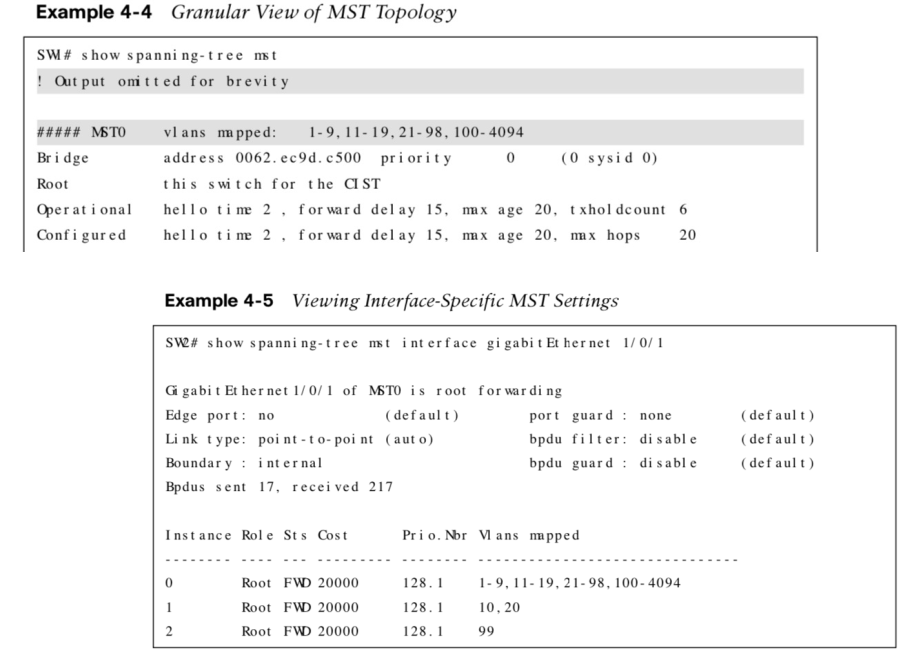
- show spanning-tree mst [instance-number].
- show spanning-tree mst interface interface-id.
MST Tuning
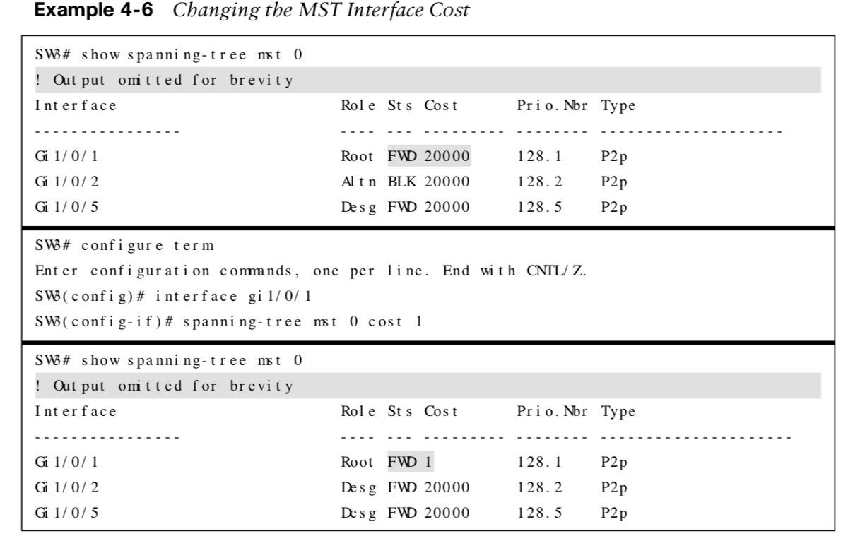 MST supports the tuning of port cost and port priority. The interface config command spanning-tree mst instance-number cost cost sets the interface cost.
 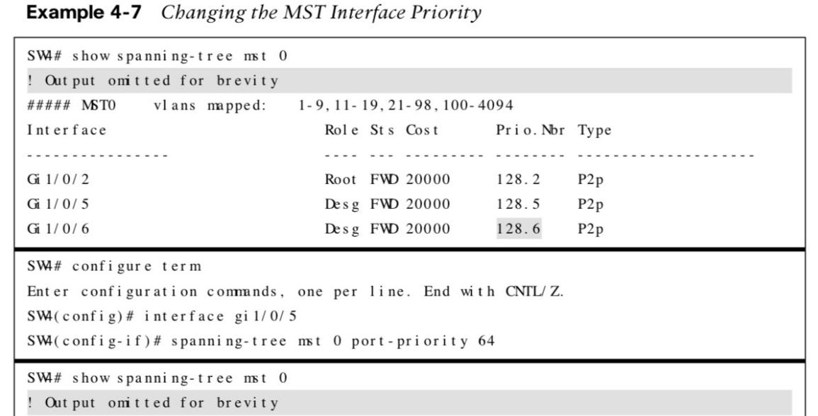 spanning-tree mst instance-number port -priority priority sets the interface priority.
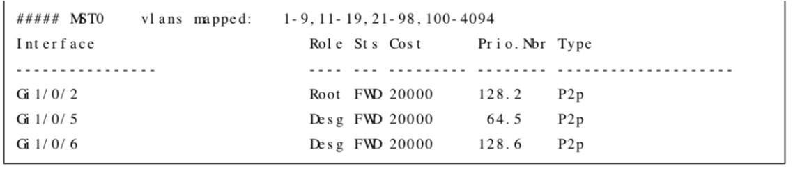
Common MST Misconfigurations
There are two common misconfigurations within the MST region:
- VLAN assignment to the IST
- Trunk link pruning
VLAN Assignment to IST

- The IST topology may not correlate to the access layer and might introduce a blocking port that was not intentional.
- In the example, it appears as if traffic between PC-A and PC-B would flow across the Gi1/0/2 interface, as it is an access port assigned to VLAN 10. However, all interfaces belong to the IST instance.
- SW2 must block either Gi1/0/1 or Gi1/0/2. Since SW1 is the root bridge, SW2 blocks Gi1/0/2 based on the port identifier from SW1. Therefore, blocking the IST instance.
- There are two solutions for this scenario:
- Move VLAN 10 to an MSTI instance other than the IST. If you do this, the switches will build a topology based on the links in use by that MSTI.
- Allow the VLANs associated with the IST on all interswitch (trunk) links.
Trunk Link Pruning
Pruning of VLANs on a trunk link is a common practice for load balancing. However, it is important that pruning of VLANs does not occur for VLANs in the same MST on different network links. 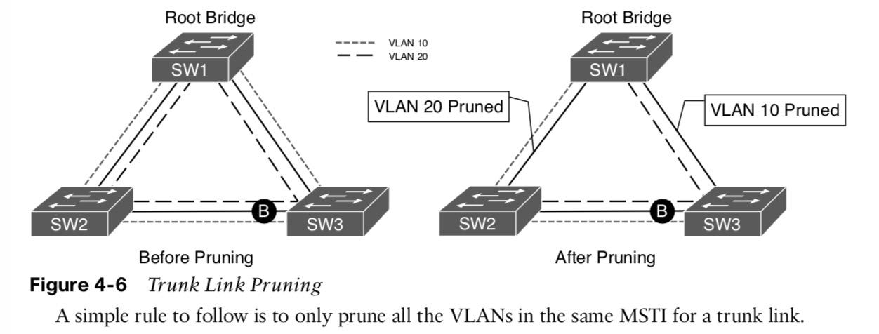
- Links between SW1 to SW2 and SW1 to SW3 have been pruned to help with load balancing traffic.
- After implementing the changes, users attached to SW1 and SW3 can no longer communicate with the servers on SW1.
- This is due to the VLANs on the trunk links changing but not the MSTI topology.
MST Region Boundary
- An MST region boundary is any port that connects to a switch that is in a different MST region or that connects to 802.1D or 802.1W BPDUs.
- MSTI’s never interact outside of the region and MST switches can detect PVST+ neighbors at MST region boundaries.
- Propagating CST at the MST region boundary involves a feature called PVST simulation mechanism. It sends out PVST+ & RSTP BPDUs, one for each VLAN.
- The PVST simulation mechanism required because PVST+/RSTP topologies do not understand the structure of IST BPDUs.
- When the MST boundary receives the PVST+ BPDU it doesn’t map the VLAN to the MSTI. Instead the MST boundary maps the PVST+ BPDU from VLAN 1 to the instance.
- It only does this when it receives a PVST BPDU on a port.
MST Region Design Considerations
There are two design considerations when integrating an MST region with a PVST+/RSTP environment:
- MST region as the root bridge
- MST region is not a root bridge for any VLAN
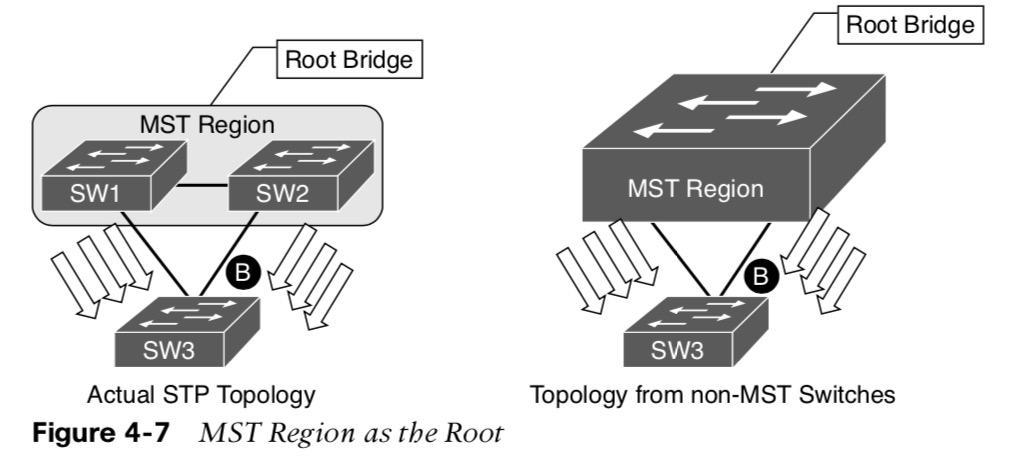
MST Region as the Root Bridge
The MST region as the root bridge ensures that all region boundary ports flood the same IST instance BPDU to all the VLANs in the PVST topology. This makes the IST instance preferred over any other switch in the PVST+ topology. The MST region appears as a single device and the PVST+ switches detect and place the alternative link into a blocking state.
MST Region Not a Root Bridge for Any VLAN
- In the situation that the MST region is not a root bridge for any VLAN, the MST region boundary ports can only block or forward for all VLANs.
- There is not an option to load balance traffic because the IST instance must remain constant.
- If the MST switch detects a better BPDU for a specific VLAN on a boundary port, the switch will use BPDU guard to block the port.
- This is called PVST simulation check and it done to ensure a loop-free topology.
Other useful information: