First Hop Redundancy Protocol
gives details on how multiple routers can provide resilient gateway functionality to hosts at the L2/L3 boundaries.
- Network resiliency is a key component of network design.
- Network resiliency can be accomplished by adding redundant devices such as Layer 2 switches or Layer 3 routers into a topology.
Network Resiliency/First Hop Redundancy Protocols
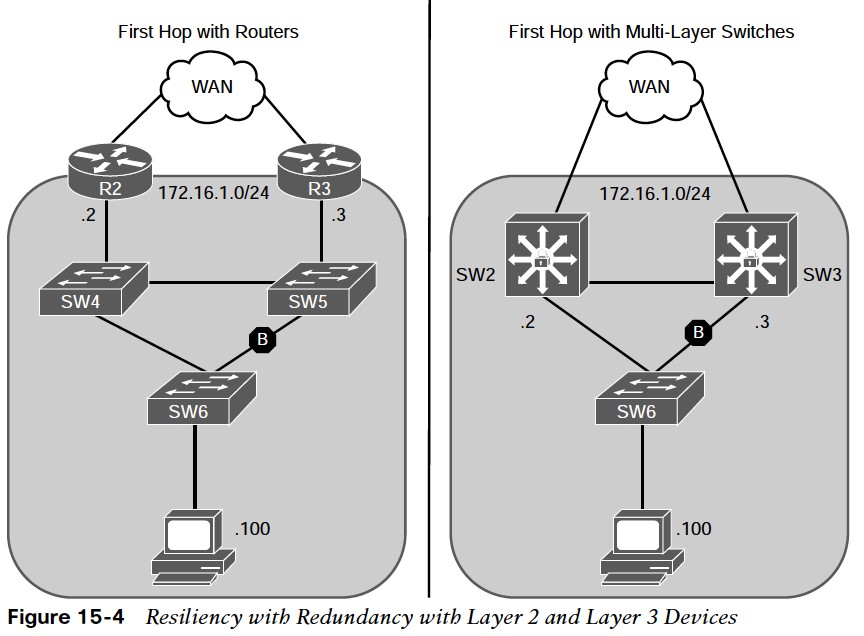
The figure shows the concept of adding resiliency to the network. In both scenarios:
- Two devices (172.16.1.2 and 172.16.1.3) can be the PC’s gateway.
- There are two resilient Layer 2 links that connect SW6 to a switch that can connect the PC to either gateway.
First-hop redundancy protocols (FHRPs) solve the problem of end devices configuring multiple gateways. They do this by creating a virtual IP (VIP) gateway that is shared between the Layer 3 devices. The following are FHRPs:
- Hot Standby Router Protocol (HSRP)
- Virtual Router Redundancy Protocol (VRRP)
- Gateway Load Balancing Protocol (GLBP)
Object Tracking
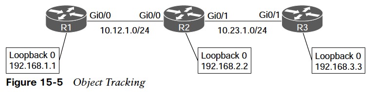 Object tracking offers a flexible and customizable mechanism for linking with FHRPs and other routing components. Users can track specific objects in the network and take necessary action when any object’s state change affects the network traffic.
 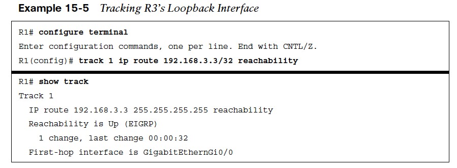 To track routes in the routing table use the command track object-number ip route route/prefix-length reachability. The status of object tracking can be viewed with the command show track [object-number].
Tracking an Interface
To track an interface’s line protocol state use the command track object-number interface interface-id line-protocol. 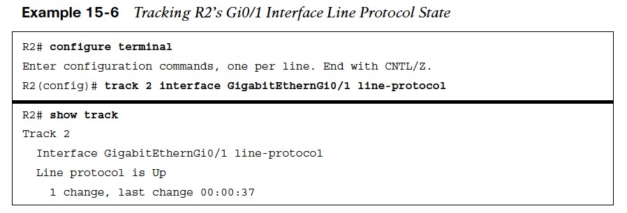
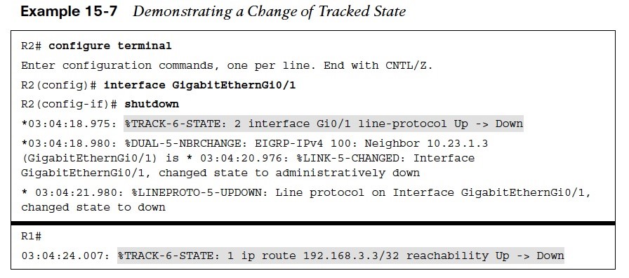
- The example shows R2 being configured for tracking the Gi0/1 interface toward R3.
- Shutting down R2’s Gi0/1 interface changed the tracked object state on R1 and R2 to a down state.
- Object tracking works with protocols such as Hot Standby Router Protocol (HSRP), Virtual Router Redundancy Protocol (VRRP), and Gateway Load Balancing Protocol (GLBP). They take action when the state of an object changes.
Hot Standby Router Protocol
Hot Standby Routing Protocol (HSRP) is a Cisco proprietary protocol. It provides routing redundancy for hosts configured with a default gateway IP address.
- A minimum of two devices are required to enable HSRP:
- One device acts as the active device and takes care of forwarding the packets.
- The other acts as a standby that is ready to take over the role of active device in the event of a failure.
- A virtual IP address is configured on each HSRP-enabled interface that belongs to the same HSRP group. A virtual MAC address is also assigned for the group.
- The active router receives and routes the packets destined for the virtual MAC address of the group.
- HSRP-enabled interfaces send and receive multicast UDP-based hello messages to detect any failure and designate active and standby routers.
- When the HSRP active router fails, the HSRP standby router assumes control of the virtual IP address and virtual MAC address of the group.
HSRP Elections & Versions
- A HSRP election selects the router with the highest priority (default is 100).
- In the event of a tie in priority, the router with the highest IP address for the network segment is preferred.
- HSRP does not support preemption by default. If a router with a lower priority becomes active, it stays active regardless if the superior router comes back online.
- The transition of the HSRP active to the standby is transparent to all hosts on the segment because the MAC address moves with the virtual IP address.
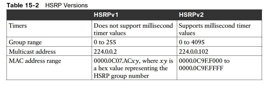
- HSRP has two versions, HSRPv1 and HSRPv2.
Configuring HSRP Virtual IP Address
The following steps show how to configure an HSRP virtual IP (VIP) gateway instance:
- Step 1. Define the HSRP instance by using the command standby instance-id ip vipaddress.
- Step 2. (Optional) Configure HSRP router preemption with the command standby instanceid preempt.
- Step 3. (Optional) Configure the HSRP priority by using the command standby instance-id priority priority. The priority is a value between 0 and 255.
- Step 4. (Optional) Configure the HSRP MAC address with the command standby instanceid mac-address mac-address.
- Step 5. (Optional) Define the HSRP timers by using the command standby instance-id timers {seconds | msec milliseconds}. HSRP can poll in intervals of 1 to 254 seconds or 15 to 999 milliseconds
- Step 6. (Optional) Establish HSRP authentication by using the command standby instanceid authentication {text-password | text text-password | md5 {key-chain key-chain | keystring key-string}}.
HSRP Configuration and State
Example 15-9 shows a basic HSRP configuration for VLAN 10 on SW1 and SW2, using the HSRP instance 10 and the VIP gateway instance 172.16.10.1. 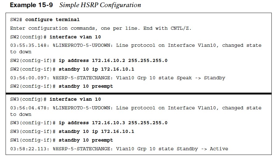
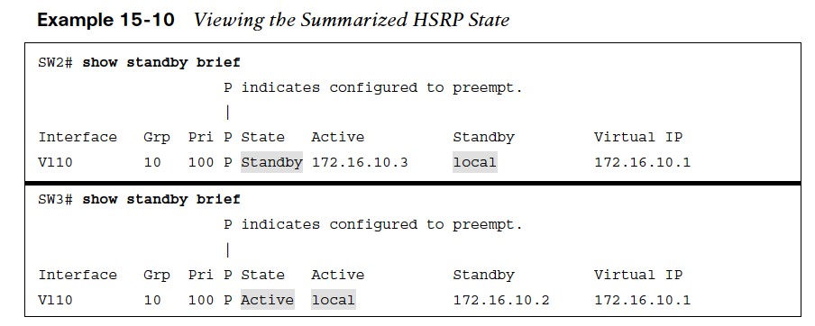
- Example 15 -10 shows the summarized HSRP status using the command show standby [interface-id] [brief].
- The show standby command gives more details into the HSRP state. It includes the number of state changes, time since last state change, VIP addresses, timers, preemption, priority and group name.
HSRP Tracked Objects
HSRP provides the capability to link object tracking to priority. 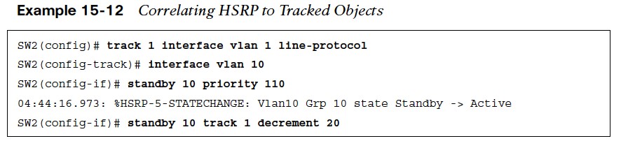
- Example 15-12 shows the configuration of SW2 where a tracked object is created against VLAN 1’s interface line protocol, increasing the HSRP priority to 110, and linking HSRP to the tracked object so that the priority decrements by 20 if interface VLAN 1 goes down.
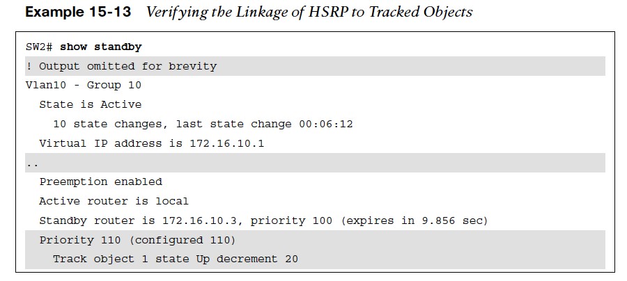
- Example 15-13 shows that the HSRP group on VLAN 10 on SW2 correlates the status of the tracked object for the VLAN 1 interface.
Verifying HSRP State With Tracked Objects
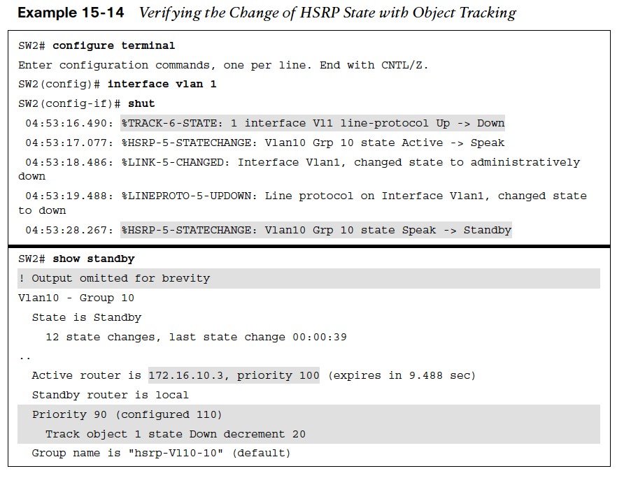 Example 15-14 verifies the anticipated behavior by shutting down the VLAN 1 interface on SW2. The syslog messages indicate that the object track state changed immediately after the interface was shut down, and shortly thereafter, the HSRP role changed to a standby state.
Virtual Router Redundancy Protocol
Virtual Router Redundancy Protocol (VRRP) is an industry standard protocol that operates similarly to HSRP. However, the differences are as follows:
- The preferred active router controlling the VIP gateway is called the master router. All other VRRP routers are known as backup routers.
- VRRP enables preemption by default.
- The MAC address of the VIP gateway uses the structure 0000.5e00.01xx, where xx reflects the group ID in hex.
- VRRP uses the multicast address 224.0.0.18 for communication.
There are currently two versions of VRRP:
- VRRPv2: Supports IPv4
- VRRPv3: Supports IPv4 and IPv6
Legacy VRRP Configuration
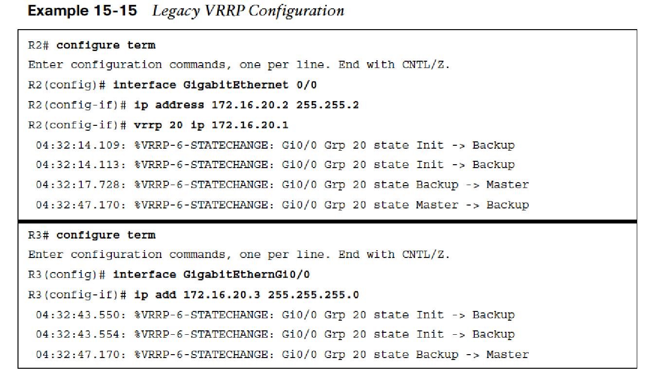
Early VRRP configurations supported only VRRPv2 and was non-hierarchical in its configuration. The following are steps used to configure older software versions with VRRP:
- Step 1. Define the VRRP instance by using the command vrrp instance-id ip vip-address.
- Step 2. (Optional) Define the VRRP priority by using the command vrrp instance-id priority priority. The priority is a value between 0 and 255.
- Step 3. (Optional) Enable object tracking so that the priority is decremented when the object is false by using the command vrrp instance-id track object-id decrement decrement-value.
- Step 4. (Optional) Establish VRRP authentication by using the command vrrp instance-id authentication {textpassword | text text-password | md5 {key-chain keychain | key-string key-string}}
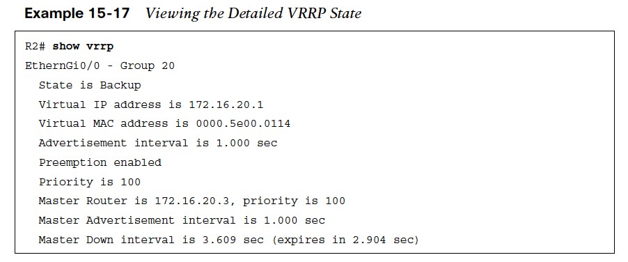
VRRP State
The command show vrrp [brief] provides an update on the VRRP group, along with other relevant information for troubleshooting. Example 15-16 shows the brief iteration of the command and 15-17 shows the detailed state of VRRP. 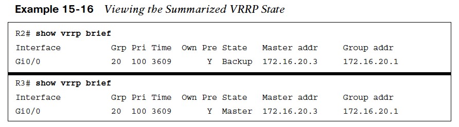
Hierarchical VRRP Configuration
The newer version of IOS XE software provides configuration of VRRP in a multi-address format that is hierarchical. The following are steps to configure hierarchical VRRP: 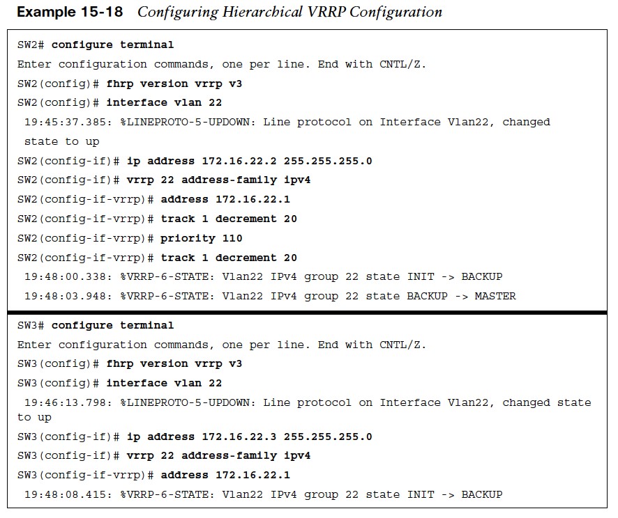
- Step 1. Enable VRRPv3 on the router by using the command fhrp version vrrp v3.
- Step 2. Define the VRRP instance by using the command vrrp instance-id address-family {ipv4 | ipv6}.
- Step 3. (Optional) Change VRRP to Version 2 by using the command vrrpv2. VRRPv2 and VRRPv3 are not compatible. Step 4. Define the gateway VIP by using the command address ip-address.
- Step 5. (Optional) Define the VRRP priority by using the command priority priority.
- Step 6. (Optional) Enable object tracking so that the priority is decremented when the object is false using the command track object-id decrement decrement-value.
The status of the VRRP routers can be viewed with the command show vrrp [brief]. The output is identical to that of the legacy VRRP configuration.
Global Load Balancing Protocol
Global Load Balancing Protocol (GLBP) provides gateway redundancy and load-balancing capability to a network segment. It does this with an active/standby gateway and ensures that each member of the GLBP group forwards traffic to the appropriate gateway. The GLBP has two roles:
- Active virtual gateway (AVG): The participating routers elect one AVG per GLBP group to respond to initial ARP requests for the VIP.
- Active virtual forwarder (AVF): The AVF routes traffic received from assigned hosts. A unique virtual MAC address is created and assigned by the AVG to the AVFs. The AVF is assigned to a host when the AVG replies to the ARP request with the assigned AVF’s virtual MAC address. The AVFs are also recognized as Fwd instances on the routers.
GLBP supports four active AVFs and one AVG per GLBP group. A router can be an AVG and an AVF at the same time. In the event of a failure of the AVG, the AVG role is transferred to a standby AVG device. In the event of a failure of an AVF, another router takes over the forwarding responsibilities for that AVF, which includes the virtual MAC address for that instance.
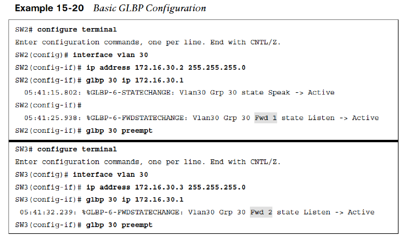
GLBP Configuration
The following steps detail how to configure a GLBP:
- Step 1. Define the GLBP instance by using the command glbp instance-id ip vip-address.
- Step 2. (Optional) Configure GLBP preemption with the command glbp instance-id preempt. Step 3. (Optional) Define the GLBP priority by using the command glbp instance-id priority priority. The priority is a value between 0 and 255.
- Step 4. (Optional) Define the GLBP timers by using the command glbp instance-id timers {hello-seconds | msec hello-milliseconds} {hold-seconds | msec hold-milliseconds}.
- Step 5. (Optional) Establish GLBP authentication by using the command glbp instance-id authentication {text text-password | md5 {key-chain key-chain | key-string key-string}}.
GLBP Status
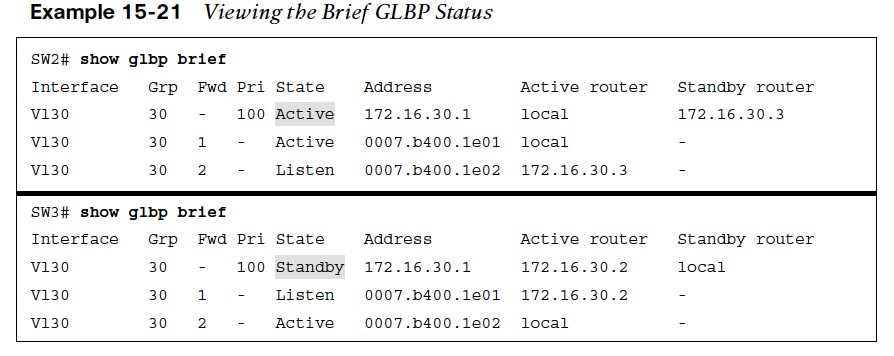
- The command show glbp brief shows high-level details of the GLBP group, including the interface, group, active AVG, standby AVG, and statuses of the AVFs.
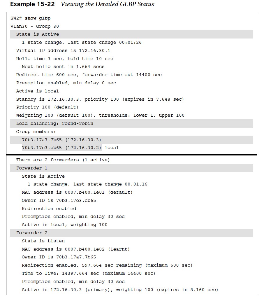
- The command show glbp displays additional information, including the timers, preemption settings, and statuses for the AVG and AVFs for the GLBP group.
GLBP Load Balancing
GLBP supports three methods of load balancing traffic:
- Round robin – Uses each virtual forwarder MAC address to sequentially reply for the virtual IP address. GLBP uses round robin as the default load-balancing method.
- Weighted – Defines weights to each device in the GLBP group to define the ratio of load balancing between the devices. This allows for a larger weight to be assigned to bigger routers that can handle more traffic.
- Host dependent – Uses the host MAC address to decide to which virtual forwarder MAC to redirect the packet. This method ensures that the host uses the same virtual MAC address as long as the number of virtual forwarders does not change within the group.
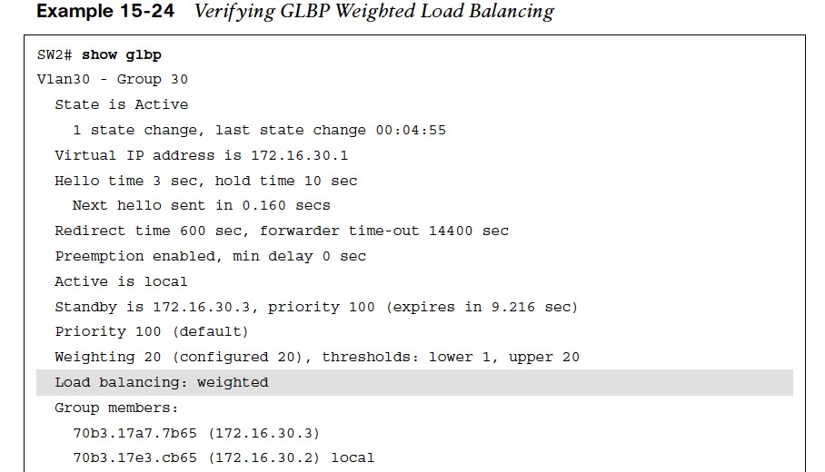
The load-balancing method can be changed with the command glbp instance-id loadbalancing {host-dependent | round-robin | weighted}. The weighted load-balancing method has the AVG direct traffic to the AVFs based on the percentage of weight a router has over the total weight of all GLBP routers. The weight can be set for a router with the command glbp instance-id weighting weight.
Verifying GLBP Weighted Load Balancing
The example shows that the load-balancing method has been changed to weighted and that the appropriate weight has been set for each AVF. 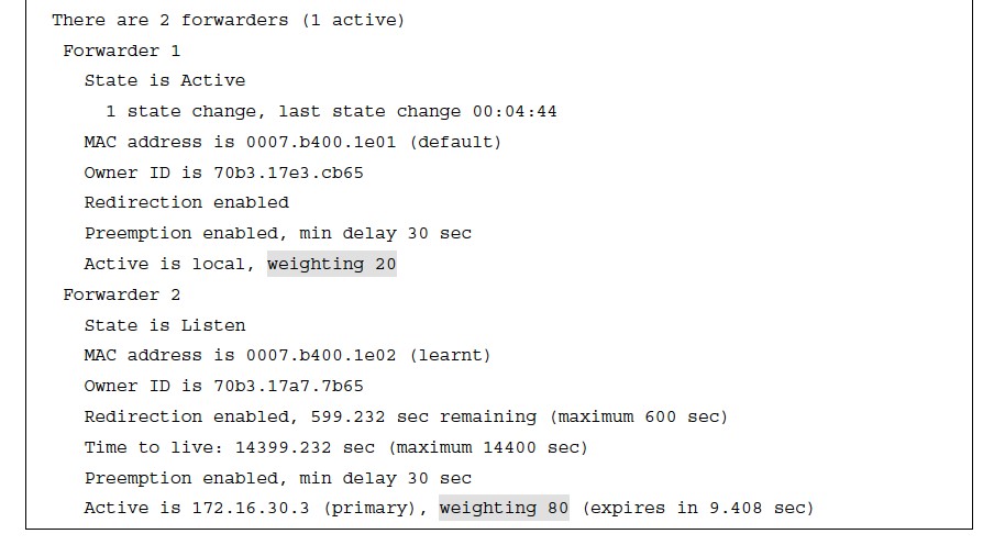
Other useful information: