EtherChannel Bundle
how multiple physical interfaces can be combined to form a logical interface to increase throughput and provide seamless resiliency.
- Ethernet network speeds are based on powers of 10 (10 Mbps, 100 Mbps, 1 Gbps, 10 Gbps,100 Gbps).
- When a link between switches becomes saturated, how can more bandwidth be added to that link to prevent packet loss?
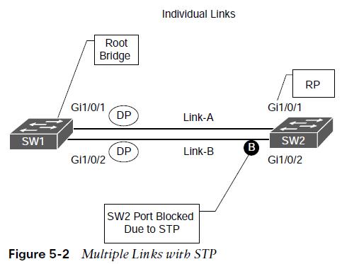
Multiple Links
Ideally, it would be nice to plug in a second cable and double the bandwidth between the switches. However, STP will place one of the ports into a blocking state to prevent forwarding loops.
EtherChannel Components
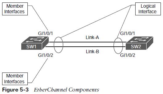 The physical links can be aggregated into a logical link called an EtherChannel bundle.
EtherChannel Components
- Etherchannel defined in the IEEE 802.3AD link aggregation specification.
- STP operates on a logical link and not on a physical link.
- The logical link will have the bandwidth of any active member interfaces.
- It will load balanced across all the links.
- EtherChannels can be used for either Layer 2 (access or trunk) or Layer 3 links.
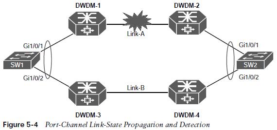
EtherChannel Link-State
- EtherChannel may be created statically or dynamically.
- Static EtherChannel does not have a health integrity check. If the physical medium degrades and keeps the line protocol in an up state, the port channel will reflect that link as viable for transferring data.
- A common scenario involves the use of intermediary devices and technologies (for example, powered network taps, IPSs, L2 firewalls, DWDM) between devices. It is critical for the link state to be propagated to the other side.
Dynamic Link Aggregation Protocols
Two common link aggregation protocols are LACP and PAgP.
- PAgP is Cisco proprietary and developed first.
- LACP was created as an open industry standard.
- All the member links must participate in the same protocol on the local and remote switches.
PAgP Port Modes
PAgP advertises messages with the multicast MAC address 0100:0CCC:CCCC and the protocol code 0x0104. PAgP can operate in two modes:
| PAgP Port Modes | Description |
| Auto | • The interface does not initiate an EtherChannel to be established and does not transmit PAgP packets out of it. • If an PAgP packet is received from the remote switch, this interface responds and then can establish a PAgP adjacency. • If both devices are PAgP auto, a PAgP adjacency does notform. |
| Desirable | • An interface tries to establish an EtherChannel and transmit PAgP packets out of it. • Active PAgP interfaces can establish a PAgP adjacency only ifthe remote interface is configured to auto or desirable. |
LACP Port Modes
LACP advertises messages with the multicast MAC address 0180:C200:0002. LACP can operate in two modes:
| LACP Port Modes | Description |
| Passive | • An interface does not initiate an EtherChannel to be established and does not transmit LACP packets out of it. • If an LACP packet is received from the remote switch, this interface responds and then can establish an LACP adjacency. • If both devices are LACP passive, an LACP adjacency does not form. |
| Active | • An interface tries to establish an EtherChannel and transmit LACP packets out of it. • Active LACP interfaces can establish an LACP adjacency only if theremote interface is configured to active or passive. |
EtherChannel Configurations
It is possible to configure EtherChannels by going into the interface configuration mode for the member interfaces and assigning them to an EtherChannel ID and configuring the appropriate mode:
- Static EtherChannel: A static EtherChannel is configured with the interface parameter command channel-group etherchannel-id mode on.
- LACP EtherChannel: An LACP EtherChannel is configured with the interface parameter command channel-group etherchannel-id mode {active | passive}.
- PAgP EtherChannel: A PAgP EtherChannel is configured with the interface parameter command channel-group etherchannel-id mode {auto | desirable} [non-silent].
- By default, PAgP ports operate in silent mode, which allows a port to establish an EtherChannel with a device that is not PAgP capable and rarely sends packets.
- Using the optional non-silent keyword requires a port to receive PAgP packets before adding it to the EtherChannel, which is recommended.
EtherChannel Configurations
The following needs to be considered with EtherChannel configuration: 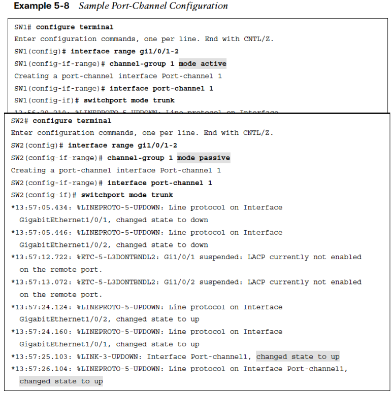
- Configuration settings for the EtherChannel are placed in the port-channel interface.
- Member interfaces need to be in the appropriate Layer 2 or Layer 3 (that is, no switch port) before being associated with the port channel.
Verify Port-Channel Status
- show etherchannel summary provides an overview of all the configured EtherChannels, along with the status and dynamic aggregation protocol for each one.
- When viewing the output of the show etherchannel summary, the first thing that should be checked is the EtherChannel status, which is listed in the Port-channel column.
- The status should be SU, as highlighted in Example 5-9.
Note: The status codes are case sensitive, so please pay attention to the case of the field. 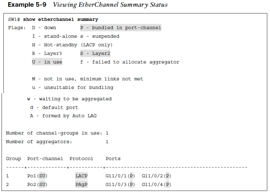
EtherChannel Logical Interface Status Fields
Logical EtherChannel Interface Status Fields are as follows:
- U – The EtherChannel is working properly.
- D – The EtherChannel is down.
- M – The EtherChannel interface has successfully established at least one LACP adjacency; however, the EtherChannel is configured with a minimum number of active interfaces that exceeds the number of active participating member interfaces. Traffic will not be forwarded across this port channel. The command port-channel min-links min-member-interfaces is configured on the port-channel interface.
- S – The port-channel interface configured for L2 switching.
- R – The port-channel interface configured for L3 routing.
EtherChannel Member Interface Status Fields EtherChannel Member Interface Status Fields are as follows:
- P – The interface is actively participating and forwarding traffic for this port channel.
- H – The port-channel is configured with the maximum number of active interfaces. This interface is participating in LACP with the remote peer, but the interface is acting as a hot standby and does not forward traffic. lacp max-bundle number-member-interfaces is configured on the port-channel.
- I – The member interface has not detected any LACP activity on this interface and is treated as an individual.
- w – There is time left to receive a packet from this neighbor to ensure that it is still alive.
- s – The member interface is in a suspended state.
- r – The switch module associated with this interface has been removed from the chassis.
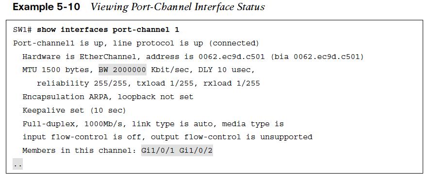
Port-Channel Interface Status
- The logical interface can be viewed with show interface port-channel port-channel-id.
- The output includes traditional interface statistics and lists the member interfaces and indicates that the bandwidth reflects the combined throughput of all active member interfaces.
EtherChannel Neighbors
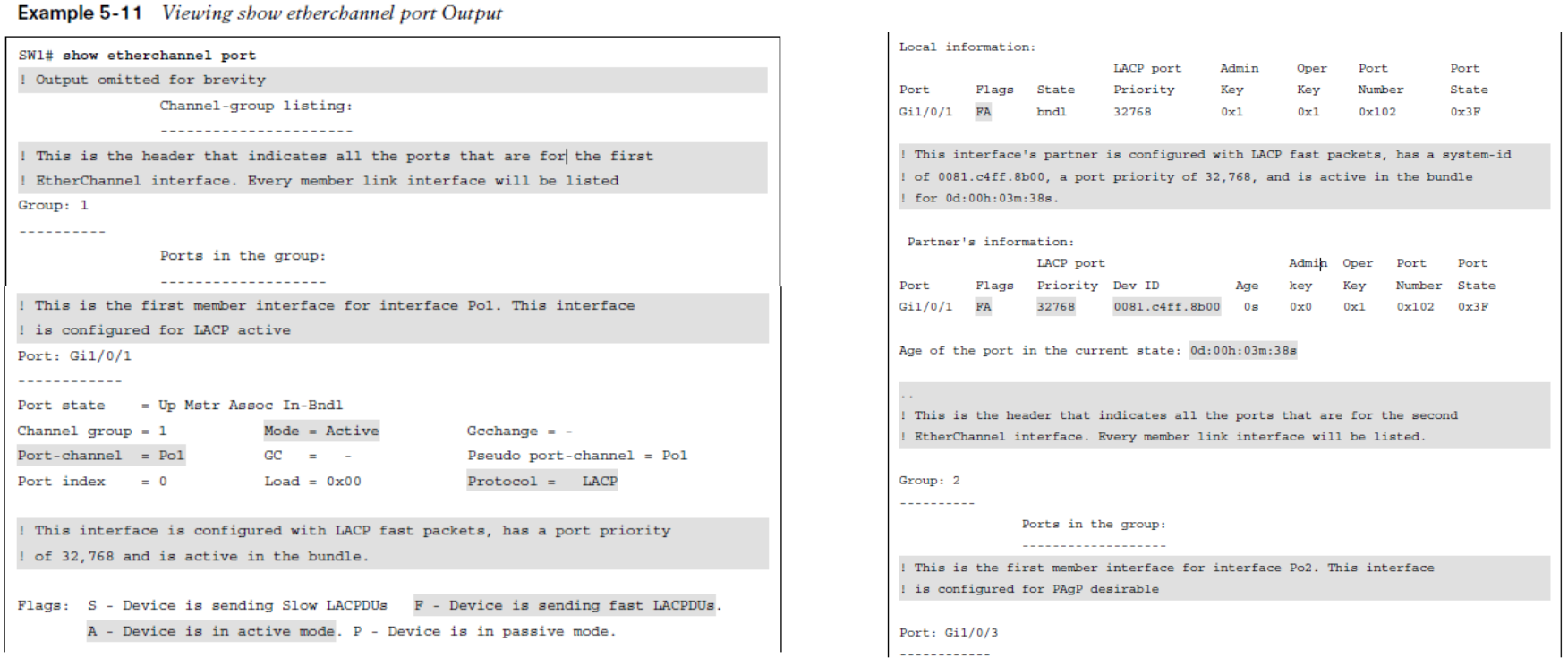
 The output from the show etherchannel port can provide too much information and slow down troubleshooting when a smaller amount of information is needed.
EtherChannel Neighbors LACP and PAgP
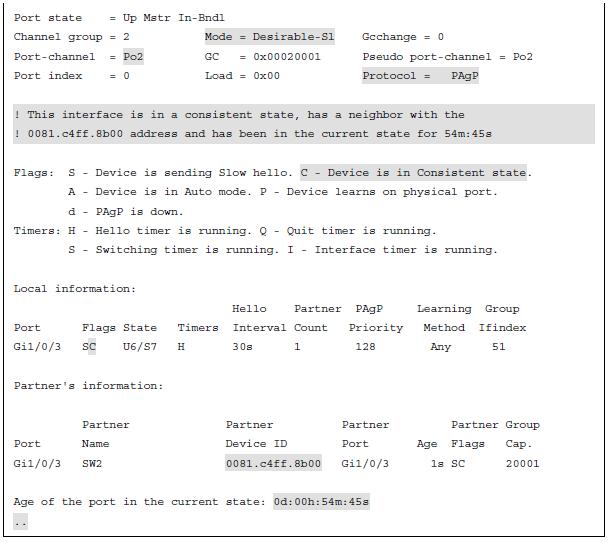
show lacp neighbor [detail] displays additional information about the LACP neighbor and includes the neighbor’s system ID, system priority, and whether it is using fast or slow LACP packet intervals as part of the output. 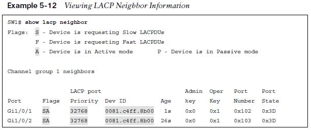 show pagp neighbor displays additional information about the PAgP neighbor and includes the neighbor’s system ID, remote port number, and whether it is using fast or slow PAgP packet intervals as part of the output.
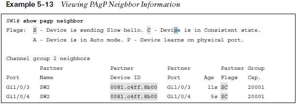
Verifying EtherChannel Packets LACP and PAgP
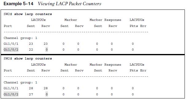 A vital step in troubleshooting the establishment of port channels is to verify that LACP or PAgP packets are being transmitted between devices. The first troubleshooting step that can be taken is to verify the EtherChannel counters for the appropriate protocol.
 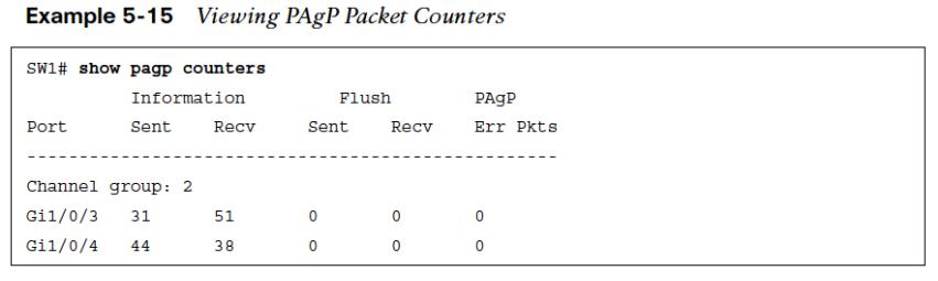 The LACP counters can be cleared with the command clear lacp counters. The PAgP counters can be cleared with the command clear pagp counters.
Advanced LACP Configuration Options
LACP provides some additional tuning that is not available with PAgP. LACP has the following advanced settings:
- LACP Fast
- Minimum Number of Port-Channel Member Interfaces
- Maximum Number of Port-Channel Member Interfaces
- LACP System Priority
- LACP Interface Priority
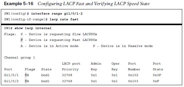
LACP Fast
- The original LACP standards sent out LACP packets every 30 seconds. A link is deemed unusable if an LACP packet is not received after three intervals, 90 seconds.
- An amendment to the standards was made so that LACP packets are advertised every 1 second. This is known as LACP fast because a link can be identified and removed in 3 seconds compared to the 90 seconds.
- LACP fast is enabled on the member interfaces with the interface configuration command lacp rate fast.
 Note: All the interfaces on both switches need to be configured the same (either using LACP fast or LACP slow) for the EtherChannel to successfully come up.
Minimum Number of Port-Channel Member Interfaces
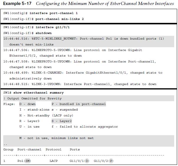
- An EtherChannel interface becomes active and up when only one member interface successfully forms an adjacency with a remote device.
- In some design scenarios using LACP, a minimum number of adjacencies is required before a port-channel interface becomes active.
- This option can be configured with the port-channel interface command port-channel min-links min-links.
The minimum number of port-channel member interfaces does not need to be configured on both devices to work properly. However, configuring it on both switches is recommended to accelerate troubleshooting and assist operational staff.
Maximum Number of Port-Channel Member Interfaces
- An EtherChannel can be configured to have a specific maximum number of member interfaces in a port channel.
- This may be done to ensure that the active member interface count proceeds with powers of two (for example, 2, 4, 8) to accommodate load-balancing hashes.
- The maximum number of member interfaces in a port channel can be configured with the port-channel interface command lacp max-bundle max-links.
 The maximum number of port-channel member interfaces needs to be configured only on the master switch for that port channel. However, configuring it on both switches is recommended to accelerate troubleshooting.
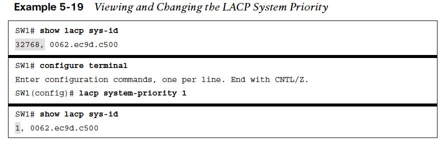
LACP System Priority
The LACP system priority identifies which switch is the master switch for a port channel.
- The master switch on a port channel is responsible for choosing which member interfaces are active in a port channel when there are more member interfaces than the maximum number of member interfaces associated with a port-channel interface.
- The switch with the lower system priority is preferred.
- The LACP system priority can be changed with the command lacp system-priority priority.
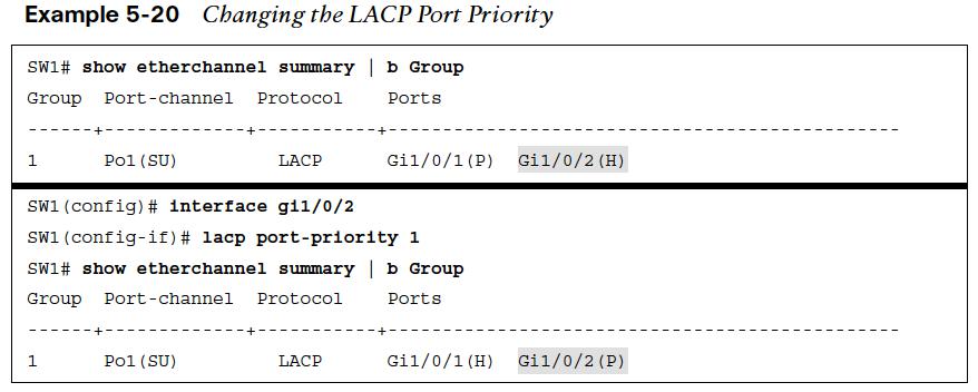
LACP Interface Priority
LACP interface priority enables the master switch to choose which member interfaces are active in a port channel when there are more member interfaces than the maximum number of member interfaces for a port channel.
- A port with a lower port priority is preferred.
- The interface configuration command lacp port-priority priority sets the interface priority.
Troubleshooting EtherChannel Bundles
A port channel is a logical interface, so all the member interfaces must have the same characteristics. If they do not, problems will occur.
- Generally as a rule, when configuring port channels on a switch, place each member interface in the appropriate switch port type (L2 or L3) and then associate the interfaces to a port channel.
- All other port-channel configuration is done via the port-channel interface.
Troubleshooting EtherChannel Bundles
The following configuration settings must match on the member interfaces: Match Settings
| Port type | Duplex |
| Port mode | MTU |
| Native VLAN | Load interval |
| Allowed VLAN | Storm control |
| Speed |
check the following when troubleshooting the establishment of an EtherChannel bundle:
- Ensure that a member link is between only two devices.
- Ensure that the member ports are all active.
- Ensure that both end links are statically set to on or that either LACP is enabled with at least one side set to active or PAgP is enabled with at least one side set to desirable.
- Ensure that all member interface ports are consistently configured (except for LACP port priority).
- Verify the LACP or PAgP packet transmission and receipt on both devices.
Load Balancing Traffic with EtherChannel Bundles
- Traffic that flows across a port-channel interface is not forwarded out member links on a round-robin basis per packet.
- Instead, a hash is calculated, and packets are consistently forwarded across a link based on that hash, which runs on the various packet header fields.
- The load-balancing hash is a system wide configuration that uses the global command port-channel load-balance hash.
Port-Channel Load Balancing Hash Option
port-channel load-balance hash. The hash option has the following keyword choices:
- dst-ip: Destination IP address
- dst-mac: Destination MAC address
- dst-mixed-ip-port: Destination IP address and destination TCP/UDP port
- dst-port: Destination TCP/UDP port
- src-dst-ip: Source and destination IP addresses
- src-dest-ip-only: Source and destination IP addresses only
- src-dst-mac: Source and destination MAC addresses
- src-dst-mixed-ip-port: Source and destination IP addresses and source and destination TCP/UDP ports
- src-dst-port: Source and destination TCP/UDP ports only
- src-ip: Source IP address
- src-mac: Source MAC address
- src-mixed-ip-port: Source IP address and source TCP/UDP port
- src-port: Source TCP/UDP port
Viewing Port-Channel Hash Algorithm
If the links are unevenly distributed, changing the hash value may provide a different distribution ratio across member links.
- For example, if a port channel is established with a router, using a MAC address as part of the hash could impact the traffic flow as the router’s MAC address does not change (as the MAC for the source or destination will always be the router’s MAC address).
- A better choice would be to use the source/destination IP address or base the hash on TCP/UDP session ports.
show etherchannel load-balance displays how a switch will load balance network traffic based on its type: non-IP, IPv4, or IPv6. 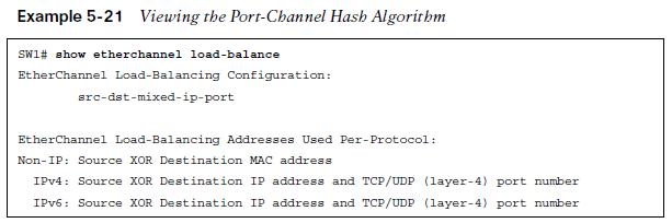 A hash is a binary function, so links should be in powers of two (for example, 2, 4, 8), to be consistent.
- A three-port EtherChannel will not load balance as effectively as a two- or four-port EtherChannel.
- The best was to view the load of each member link is with the command show etherchannel port.
Other useful information: