Common OSPF Optimizations
reviews common OSPF settings for optimizing the operation of the protocol.
- Almost every network requires tuning based on the equipment, technical requirements, or a variety of other factors.
Link Costs
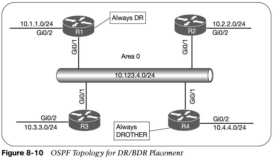
OSPF assigns the OSPF link cost for an interface using the formula in Figure 8-9. The default reference bandwidth is 100 Mbps. The command auto-cost reference-bandwidth bandwidth-in-mbps changes the reference bandwidth for all OSPF interfaces associated with that process. The OSPF cost can be set manually with the command ip ospf cost 1–65535 underneath the interface. If the value is not changed a FastEthernet interface would have the same cost as a 10 Gb interface resulting in poor routing decisions. 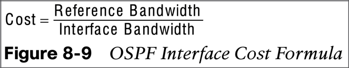
| Interface Type | OSPF Cost |
| T1 | 64 |
| Ethernet | 10 |
| FastEthernet | 1 |
| GigabitEthernet | 1 |
| 10 GigabitEthernet | 1 |
Failure Detection
- OSPF sends hello packets at set intervals based on the hello timer. OSPF uses a dead interval timer, which is four times the hello timer. If a router does not receive a hello before the OSPF dead interval timer reaches 0, the neighbor state is changed to down. The OSPF router sends out an LSA, with the topology change, and the SPF algorithm processes all routers in the area.
- OSPF allows modification to the hello timer interval with values between 1 and 65,535 seconds. The OSPF hello timer is modified with the interface configuration sub mode command ip ospf hello-interval 1–65535.
- The OSPF dead interval timer can be changed with the command ip ospf dead-interval 1– 65535 under the interface configuration sub mode. The dead interval timer setting must be greater than the hello timer setting to ensure that the dead interval timer does not reach 0 in between hello packets.
- The timers for an OSPF interfaces are shown with the command show ip ospf interface. The timers need to match on the neighboring interface.
DR and BDR Elections
- Any router with OSPF priority of 1 to 255 on its OSPF interface attempts to become the DR. By default, all OSPF interfaces use a priority of 1. The routers place their RID and OSPF priorities in their OSPF hellos for that segment.
- Routers then receive and examine OSPF hellos from neighboring routers. If the hello received is more favorable, the router updates its OSPF hello packet to use the more preferable RID in the DR field. OSPF deems a router more preferable if the priority for the interface is the highest for that segment. If the OSPF priority is the same, the higher RID is more favorable.
- After all routers agree on the same DR, all routers for that segment become adjacent with the DR. Then the election for the BDR takes place. The election follows the same logic for the DR election, except that the DR does not add its RID to the BDR field of the hello packet.
- The OSPF DR and BDR roles cannot be preempted after the DR/BDR election except for failure (or process restart of the DR or BDR).
- Determine the interface role by viewing the OSPF interface with show ip ospf interface brief.
DR and BDR Placement
- To change DR placement, modify the interface priority to a higher value than the existing DR has. The priority can be set manually under the interface configuration with the command ip ospf priority 0–255 for IOS nodes. Setting an interface priority to 0 removes that interface from the DR/BDR election immediately. Raising the priority above the default value (1) makes that interface more favorable compared to interfaces with the default value.
- Figure 8-10 provides a topology example to illustrate modification of DR/BDR placement in a network segment.
To accomplish the placement in the topology, the OSPF priority for R1 is set to 100, R2 and R3 are left at the default priority of 1, and R4 is set to 0 so that it will never become DR or BDR. R1(config)# interface G0/1 R1(config-if)# ip ospf priority 100 R4(config)# interface G0/1 R4(config-if)# ip ospf priority 0
OSPF Network Types
The default OSPF network type is based on media used for the connection. Can be changed independently of media used.
| Type | Description | DR/BDR Field in OSPF Hellos | Timers |
| Broadcast | Default setting on OSPF-enabled Ethernet links | Yes | Hello: 10, Wait: 40, Dead: 40 |
| Non-broadcast | Default setting on OSPF-enabled Frame Relay main interface or Frame Relaymultipoint subinterfaces | Yes | Hello: 30, Wait: 120, Dead: 120 |
| Point-to-point | Default setting on OSPF-enabled Frame Relay point-to-point subinterfaces. | No | Hello: 10, Wait: 40, Dead: 40 |
| Point-to-multipoint | Not enabled by default on any interface type. Interface advertised as a host route. Sets thenext-hop address to the outbound interface. | No | Hello: 30, Wait: 120, Dead: 120 |
| Loopback | Default setting on OSPF-enabled loopback interfaces. Interface is advertised as a host route (/32). | N/A | N/A |
Broadcast, Point-to-Point and Loopback Networks
- Broadcast: Broadcast networks are multiaccess in that they are capable of connecting more than two devices. A DR is required for OSPF broadcast networks because of the possibility that multiple nodes can exist on a segment, and LSA flooding needs to be controlled. The interface parameter command ip ospf network broadcast overrides the automatically configured setting and statically sets an interface as an OSPF broadcast network type.
- P2P: A network circuit that allows only two devices to communicate is considered a point-to-point (P2P) network. Only two nodes can exist on this type of network so no DR is required. The hello timer is set to 10 seconds and there is no wait timer. The interface parameter command ip ospf network point-to-point sets an interface as an OSPF point-to-point network type.
- Loopback: The OSPF network type loopback is enabled by default for loopback interfaces and can be used only on loopback interfaces. The OSPF loopback network type states that the IP address is always advertised with a /32 prefix length, even if the IP address configured on the loopback interface does not have a /32 prefix length.
Other useful information: