Classification and Marking
is used to identify and assign IP traffic into different traffic classes. Marking is used to mark packets with a specified priority based on classification or traffic conditioning policies.
- IP traffic must first be identified and categorized into different classes, based on business requirements.
- Network devices use classification to identify IP traffic as belonging to a specific class.
- Marking can be used to mark or color individual packets so that other network devices can apply QoS mechanisms to those packets.
Classification
Once an IP packet is classified, packets can then be marked/re-marked, queued, policed, shaped, or any combination of these and other actions. The following traffic descriptors are typically used for classification:
- Internal – QoS groups (locally significant to a router)
- Layer 1 – Physical interface, subinterface, or port
- Layer 2 – MAC address and 802.1Q/p Class of Service (CoS) bits
- Layer 2.5 – MPLS Experimental (EXP) bits
- Layer 3 – Differentiated Services Code Points (DSCP), IP Precedence (IPP), and source/destination IP address
- Layer 4 – TCP or UDP ports
- Layer 7 – Next Generation Network-Based Application Recognition (NBAR2)
Layer 7 Classification
NBAR2 is a deep packet inspection engine that can classify and identify a wide variety of protocols and applications using Layer 3 to Layer 7 data. NBAR2 can recognize more than 1000 applications, and monthly protocol packs are provided for recognition of new and emerging applications, without requiring an IOS upgrade or router reload. NBAR2 has two modes of operation:
- Protocol Discovery – enables NBAR2 to discover and get real-time statistics on applications currently running in the network. These statistics from the Protocol Discovery mode can be used to define QoS classes and policies using MQC configuration.
- Modular QoS CLI (MQC) – Using MQC, network traffic matching a specific network protocol such as Cisco Webex can be placed into one traffic class, while traffic that matches a different network protocol such as YouTube can be placed into another traffic class. After traffic has been classified in this way, different QoS policies can be applied to the different classes of traffic.
Marking
Packet marking is a QoS mechanism that colors a packet by changing a field within a packet or a frame header with a traffic descriptor so it is distinguished from other packets during the application of other QoS mechanisms (such as re-marking, policing, queuing, or congestion avoidance). The following traffic descriptors are used for marking traffic:
- Internal – QoS groups
- Layer 2 – 802.1Q/p Class of Service (CoS) bits
- Layer 2.5 – MPLS Experimental (EXP) bits
- Layer 3 – Differentiated Services Code Points (DSCP) and IP Precedence (IPP)
QoS groups are used to mark packets as they are received and processed internally within the router and are automatically removed when packets egress the router. They are used only in special cases in which traffic descriptors marked or received on an ingress interface would not be visible for packet classification on egress interfaces due to encapsulation or de-encapsulation.
Layer 2 Marking
- The 802.1Q standard is an IEEE specification for implementing VLANs in Layer 2 switched networks. The 802.1Q specification defines two 2-byte fields: Tag Protocol Identifier (TPID) and Tag Control Information (TCI), which are inserted within an Ethernet frame following the Source
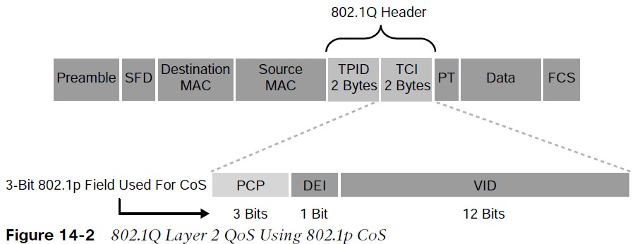 Address field, as illustrated in Figure 14-2.
- The TPID value is a 16-bit field assigned the value 0x8100 that identifies it as an 802.1Q tagged frame.
- The TCI field is a 16-bit field composed of the following three fields:
- Priority Code Point (PCP) field (3 bits)
- Drop Eligible Indicator (DEI) field (1 bit)
- VLAN Identifier (VLAN ID) field (12 bits)
Priority Code Point (PCP)
| PCP Value/Priority | Acronym | Traffic Type |
| 0 (lowest) | BK | Background |
| 1 | BE | Best Effort |
| 2 | EE | Excellent Effort |
| 3 | CA | Critical Application |
| 4 | VI | Video with < 100 ms latency and jitter |
| 5 | VO | Voice with < 10 ms latency and jitter |
| 6 | IC | Internetwork Control |
| 7 (highest) | NC | Network Control |
- The specifications of the 3-bit PCP field are defined by the IEEE 802.1p specification.
- This field is used to mark packets as belonging to a specific CoS.
- The CoS marking allows a Layer 2 Ethernet frame to be marked with eight different levels of priority values, 0 to 7, where 0 is the lowest priority and 7 is the highest.
Priority Code Point (PCP)
- One drawback of using CoS is that frames lose their CoS markings when traversing a non802.1Q link or a Layer 3 network. For this reason, packets should be marked with other higherlayer markings. This is typically accomplished by mapping a CoS marking into another marking.
- For example, the CoS priority levels correspond directly to IPv4’s IP Precedence Type of Service (ToS) values so they can be mapped directly to each other.
- Drop Eligible Indicator (DEI): The DEI field is a 1-bit field that can be used independently or in conjunction with PCP to indicate frames that are eligible to be dropped during times of congestion. The default value for this field is 0 = not drop eligible; set to 1 = is drop eligible.
- VLAN ID: The VLAN ID field is a 12-bit field that defines the VLAN used by 802.1Q.
Layer 3 Marking
Using marking at L3 provides a more persistent marker that is preserved end-to-end. 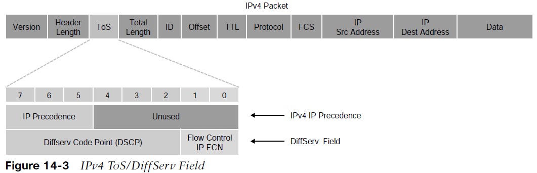
- The ToS field is an 8-bit field. Only the first 3 bits of the ToS field, referred to as IP Precedence (IPP), are used for marking, and the rest of the bits are unused. IPP values, which range from 0 to 7, allow the traffic to be partitioned in up to six usable classes of service; IPP 6 and 7 are reserved for internal network use.
- Newer standards have redefined the IPv4 ToS and the IPv6 Traffic Class fields as an 8-bit Differentiated Services (DiffServ) field. The DiffServ field uses the same 8 bits that were previously used for the IPv4 ToS and the IPv6 Traffic Class fields, and this allows it to be backward compatible with IP Precedence. The DiffServ field uses the same 8 bits that were previously used for the IPv4 ToS and the IPv6 Traffic Class fields, and this allows it to be backward compatible with IP Precedence.
DSCP Per-Hop Behaviors
- The DiffServ field is used to mark packets according to their classification into DiffServ Behavior
- Aggregates (BAs). A DiffServ BA is a collection of packets with the same DiffServ value crossing a link in a particular direction. Per-hop behavior (PHB) is the externally observable forwarding behavior (forwarding treatment) applied at a DiffServ-compliant node to a collection of packets with the same DiffServ value crossing a link in a particular direction (DiffServ BA).
- PHB is expediting, delaying, or dropping a collection of packets by one or multiple QoS mechanisms on a per-hop basis, based on the DSCP value. A DiffServ BA could be multiple applications marked with the same DSCP value.
Four PHBs have been defined and characterized for general use:
- Class Selector (CS) PHB – The first 3 bits of the DSCP field are used as CS bits. The CS bits make DSCP backward compatible with IP Precedence because IP Precedence uses the same 3 bits to determine class.
- Default Forwarding (DF) PHB – Used for best-effort service.
- Assured Forwarding (AF) PHB – Used for guaranteed bandwidth service.
- Expedited Forwarding (EF) PHB – Used for low-delay service.
Class Selector PHB
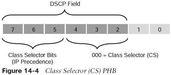 Class Selector (CS) PHB RFC 2474 made the ToS field obsolete by introducing the DiffServ field, and the Class Selector (CS) PHB was defined to provide backward compatibility for DSCP with IP Precedence.
- The last 3 bits of the DSCP (bits 2 to 4), when set to 0, identify a Class Selector PHB, but the Class Selector bits 5 to 7 are the ones where IP Precedence is set. Bits 2 to 4 are ignored by non-DiffServ-compliant devices performing classification based on IP Precedence.
- There are eight CS classes, ranging from CS0 to CS7, that correspond directly with the eight IP Precedence values.
Default Forwarding (DF) PHB
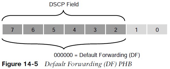 Default Forwarding (DF) PHB Default Forwarding (DF) and Class Selector 0 (CS0) provide besteffort behavior and use the DS value 000000.
- Default best-effort forwarding is also applied to packets that cannot be classified by a QoS mechanism such as queueing, shaping, or policing.
- This usually happens when a QoS policy on the node is incomplete or when DSCP values are outside the ones that have been defined for the CS, AF, and EF PHBs.
Assured Forwarding (AF) PHB

- The AF PHB guarantees a certain amount of bandwidth to an AF class and allows access to extra bandwidth, if available.
- Packets requiring AF PHB should be marked with DSCP value aaadd0, where aaa is the binary value of the AF class (bits 5 to 7), and dd (bits 2 to 4) is the drop probability where bit 2 is unused and always set to 0. Figure 14-6 illustrates the AF PHB.
- There are four standard-defined AF classes: AF1, AF2, AF3, and AF4.
- The AF class number does not represent precedence. AF4 does not get any preferential treatment over AF1. Each class should be treated independently.
Assured Forwarding (AF) PHB (Cont.)
| AF Class Name | AF IP Procedure Dec (x) | AF IP Procedure Bin | Drop Probability | Drop Probability Value Bin | Drop Probability Value Dec (y) | AF Name (Afxy) | DSCP Value Bin | DS CP Val ue De c |
| AF1 | 1 | 001 | Low | 01 | 1 | AF11 | 001010 | 10 |
| AF1 | 1 | 001 | Medium | 10 | 2 | AF12 | 001100 | 12 |
| AF1 | 1 | 001 | High | 11 | 3 | AF13 | 001110 | 14 |
| AF2 | 2 | 010 | Low | 01 | 1 | AF21 | 010010 | 18 |
| AF2 | 2 | 010 | Medium | 10 | 2 | AF22 | 010100 | 20 |
| AF2 | 2 | 010 | High | 11 | 3 | AF23 | 010110 | 22 |
| AF3 | 3 | 011 | Low | 01 | 1 | AF31 | 011010 | 26 |
| AF3 | 3 | 011 | Medium | 10 | 2 | AF32 | 011100 | 28 |
| AF3 | 3 | 011 | High | 11 | 3 | AF33 | 011110 | 30 |
| AF4 | 4 | 100 | Low | 01 | 1 | AF41 | 100010 | 34 |
| AF4 | 4 | 100 | Medium | 10 | 2 | AF42 | 100100 | 36 |
| AF4 | 4 | 100 | High | 11 | 3 | AF43 | 100110 | 38 |
Table 14-3 illustrates how each AF class is assigned an IP Precedence (under AF Class Value Bin) and has three drop probabilities: low, medium, and high.
- The AF Name (AFxy) is composed of the AF IP Precedence value in decimal (x) and the Drop Probability value in decimal (y).
- For example, AF41 is a combination of IP Precedence 4 and Drop Probability 1.
- To quickly convert the AF Name into a DSCP value in decimal, use the formula 8x + 2y. For example, the DSCP value for AF41 is 8(4) + 2(1) = 34.
Assured Forwarding (AF) and WRED
- An AF implementation must detect and respond to long-term congestion within each class by dropping packets using a congestion-avoidance algorithm such as weighted random early detection (WRED).
- WRED uses the AF Drop Probability value within each class—where 1 is the lowest possible value, and 3 is the highest possible—to determine which packets should be dropped first during periods of congestion.
- It should also be able to handle short-term congestion resulting from bursts if each class is placed in a separate queue, using a queueing algorithm such as class-based weighted fair queueing (CBWFQ). The AF specification does not define the use of any particular algorithms to use for queueing and congestion avoidance, but it does specify the requirements and properties of such algorithms.
Expedited Forwarding (EF) PHB
The EF PHB can be used to build a low-loss, low-latency, low-jitter, assured bandwidth, end-to-end service.
- The EF PHB guarantees bandwidth by ensuring a minimum departure rate and provides the lowest possible delay by implementing low-latency queueing.
- It also prevents starvation of other applications or classes that are not using the EF PHB by policing EF traffic when congestion occurs.
- Packets requiring EF should be marked with DSCP binary value 101110 (46 in decimal). Bits 5 to 7 (101) of the EF DSCP value map directly to IP Precedence 5 for backward compatibility .
Scavenger Class
The scavenger class is intended to provide less than best-effort services. Applications assigned to the scavenger class have little or no contribution to the business objectives of an organization and are typically entertainment-related applications. These include:
- peer-to-peer applications (such as Torrent),
- gaming applications (for example, Minecraft, Fortnite), and
- entertainment video applications (for example, YouTube, Vimeo, Netflix).
These types of applications are usually heavily rate limited or blocked entirely.
- Something very peculiar about the scavenger class is that it is intended to be lower in priority than a best-effort service.
- Best-effort traffic uses a DF PHB with a DSCP value of 000000 (CS0). Since there are no negative DSCP values, it was decided to use CS1 as the marking for scavenger traffic. This is defined in RFC 4594.
Trust Boundary
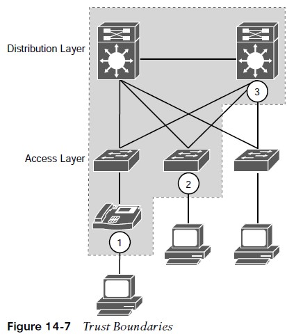
Packets should be marked by the endpoint or as close to the endpoint as possible.
- When an endpoint marks a frame or a packet with a CoS or DSCP value, the switch port it is attached to can be configured to accept or reject the CoS or DSCP values.
- If the switch accepts the values, it means it trusts the endpoint and does not need to do any packet reclassification and re-marking for the received endpoint’s packets.
- If the switch does not trust the endpoint, it rejects the markings and reclassifies and re-marks the received packets with the appropriate CoS or DSCP value.
- For example, consider a campus network with IP telephony and host endpoints; the IP phones by default mark voice traffic with a CoS value of 5 and a DSCP value of 46 (EF), while incoming traffic from an endpoint (such as a PC) attached to the IP phone’s switch port is re-marked to a CoS value of 0 and a DSCP value of 0.
- Even if the endpoint is sending tagged frames with a specific CoS or DSCP value, the default behavior for Cisco IP phones is to not trust the endpoint and zero out the CoS and DSCP values before sending the frames to the switch. When the IP phone sends voice and data traffic to the switch, the switch can classify voice traffic as higher priority than the data traffic, thanks to the highpriority CoS and DSCP markings for voice traffic.
Trust Boundary Example (Cont.)
- The IP phones by default mark voice traffic with a CoS value of 5 and a DSCP value of 46 (EF), while incoming traffic from an endpoint (such as a PC) attached to the IP phone’s switch port is re-marked to a CoS value of 0 and a DSCP value of 0.
- Even if the endpoint is sending tagged frames with a specific CoS or DSCP value, the default behavior for Cisco IP phones is to not trust the endpoint and zero out the CoS and DSCP values before sending the frames to the switch. When the IP phone sends voice and data traffic to the switch, the switch can classify voice traffic as higher priority than the data traffic, thanks to the high-priority CoS and DSCP markings for voice traffic.
- Figure 14-7 illustrates trust boundaries at different points in a campus network, where 1 and 2 are optimal, and 3 is acceptable only when the access switch is not capable of performing classification.
A Practical Example: Wireless QoS
A wireless network can be configured to leverage the QoS mechanisms. For example, a wireless LAN controller (WLC) sits at the boundary between wireless and wired networks, so it becomes a natural location for a QoS trust boundary.
- Traffic entering and exiting the WLC can be classified and marked so that it can be handled appropriately as it is transmitted over the air and onto the wired network.
- Wireless QoS can be uniquely defined on each wireless LAN (WLAN), using the four traffic categories listed in table below. Notice that the category names are human-readable words that translate to specific 802.1p and DSCP values.
| QoS Category | Traffic Type | 8021.p Tag | DSCP Value |
| Platinum | Voice | 5 | 46 (EF) |
| Gold | Video | 4 | 34 (AF41) |
| Silver | Best Effort (Default) | 0 | 0 |
| Bronze | Background | 1 | 10 (AF11) |
A Practical Example: Wireless QoS
- When you create a new WLAN, its QoS policy defaults to Silver, or best-effort handling.
- WLAN named ‘voice’ has been created to carry voice traffic, so its QoS policy has been set to Platinum. Wireless voice traffic will then be classified for low latency and low jitter and marked with an 802.1p CoS value of 5 and a DSCP value of 46 (EF).
 Figure 14-8 Setting the QoS Policy for a Wireless LAN
Other useful information: