Routing Concepts
Module Objective: Explain how routers use information in packets to make forwarding decisions.
| Topic Title | Topic Objective |
|---|---|
| Path Determination | Explain how routers determine the best path. |
| Packet Forwarding | Explain how routers forward packets to the destination. |
| Basic Router Configuration Review | Configure basic settings on a router. |
| IP Routing Table | Describe the structure of a routing table. |
| Static and Dynamic Routing | Compare static and dynamic routing concepts. |
14.1 Path Determination
Two Functions of a Router
When a router receives an IP packet on one interface, it determines which interface to use to forward the packet to the destination. This is known as routing. The interface that the router uses to forward the packet may be the final destination, or it may be a network connected to another router that is used to reach the destination network. Each network that a router connects to typically requires a separate interface, but this may not always be the case. The primary functions of a router are to determine the best path to forward packets based on the information in its routing table, and to forward packets toward their destination.
Router Functions Example
- The best path in the routing table is also known as the longest match.
- The routing table contains route entries consisting of a prefix (network address) and prefix length. For there to be a match between the destination IP address of a packet and a route in the routing table, a minimum number of far-left bits must match between the IP address of the packet and the route in the routing table. The prefix length of the route in the routing table is used to determine the minimum number of far-left bits that must match.
- The longest match is the route in the routing table that has the greatest number of far-left matching bits with the destination IP address of the packet. The longest match is always the preferred route.
Note: The term prefix length will be used to refer to the network portion of both IPv4 and IPv6 addresses.
IPv4 Longest Match Example
In the table, an IPv4 packet has the destination IPv4 address 172.16.0.10. The router has three route entries in its IPv4 routing table that match this packet: 172.16.0.0/12, 172.16.0.0/18, and 172.16.0.0/26. Of the three routes, 172.16.0.0/26 has the longest match and would be chosen to forward the packet. For any of these routes to be considered a match there must be at least the number of matching bits indicated by the subnet mask of the route. 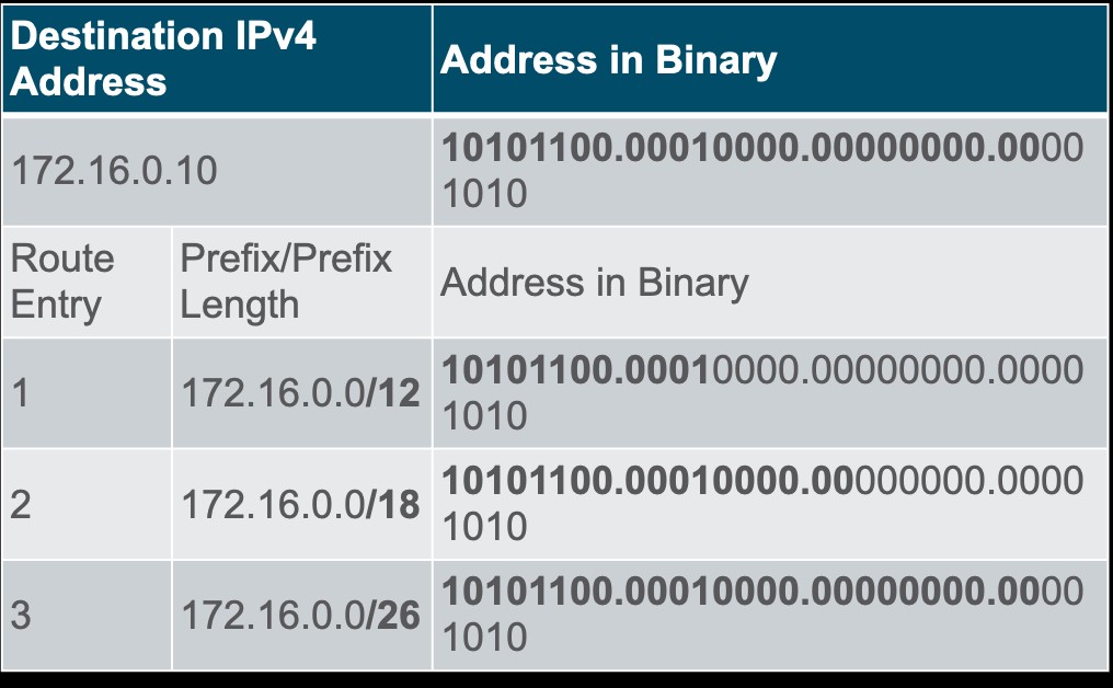
IPv6 Longest Match Example
An IPv6 packet has the destination IPv6 address 2001:db8:c000::99. This example shows three route entries, but only two of them are a valid match, with one of those being the longest match. The first two route entries have prefix lengths that have the required number of matching bits as indicated by the prefix length. The third route entry is not a match because its /64 prefix requires 64 matching bits. 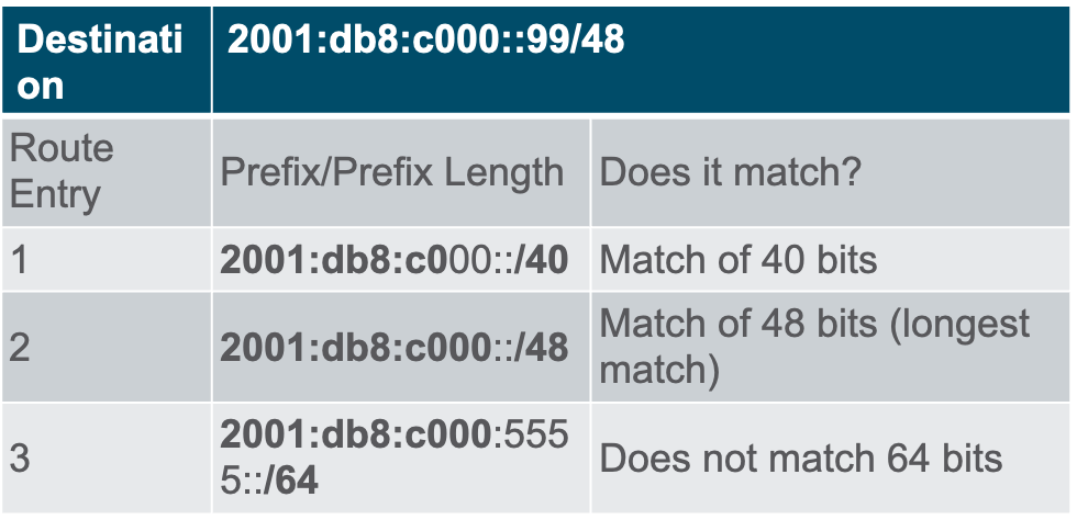
Build the Routing Table
Directly Connected Networks: Added to the routing table when a local interface is configured with an IP address and subnet mask (prefix length) and is active (up and up). Remote Networks: Networks that are not directly connected to the router. Routers learn about remote networks in two ways:
- Static routes – Added to the routing table when a route is manually configured.
- Dynamic routing protocols – Added to the routing table when routing protocols dynamically learn about the remote network.
Default Route: Specifies a next-hop router to use when the routing table does not contain a specific route that matches the destination IP address. The default route can be entered manually as a static route, or learned automatically from a dynamic routing protocol.
- A default route has a /0 prefix length. This means that no bits need to match the destination IP address for this route entry to be used. If there are no routes with a match longer than 0 bits, the default route is used to forward the packet. The default route is sometimes referred to as a gateway of last resort.
14.2 Packet Forwarding
Packet Forwarding Decision Process
1. The data link frame with an encapsulated IP packet arrives on the ingress interface. 2. The router examines the destination IP address in the packet header and consults its IP routing table. 3. The router finds the longest matching prefix in the routing table. 4. The router encapsulates the packet in a data link frame and forwards it out the egress interface. The destination could be a device connected to the network or a next-hop router. 5. However, if there is no matching route entry the packet is dropped. 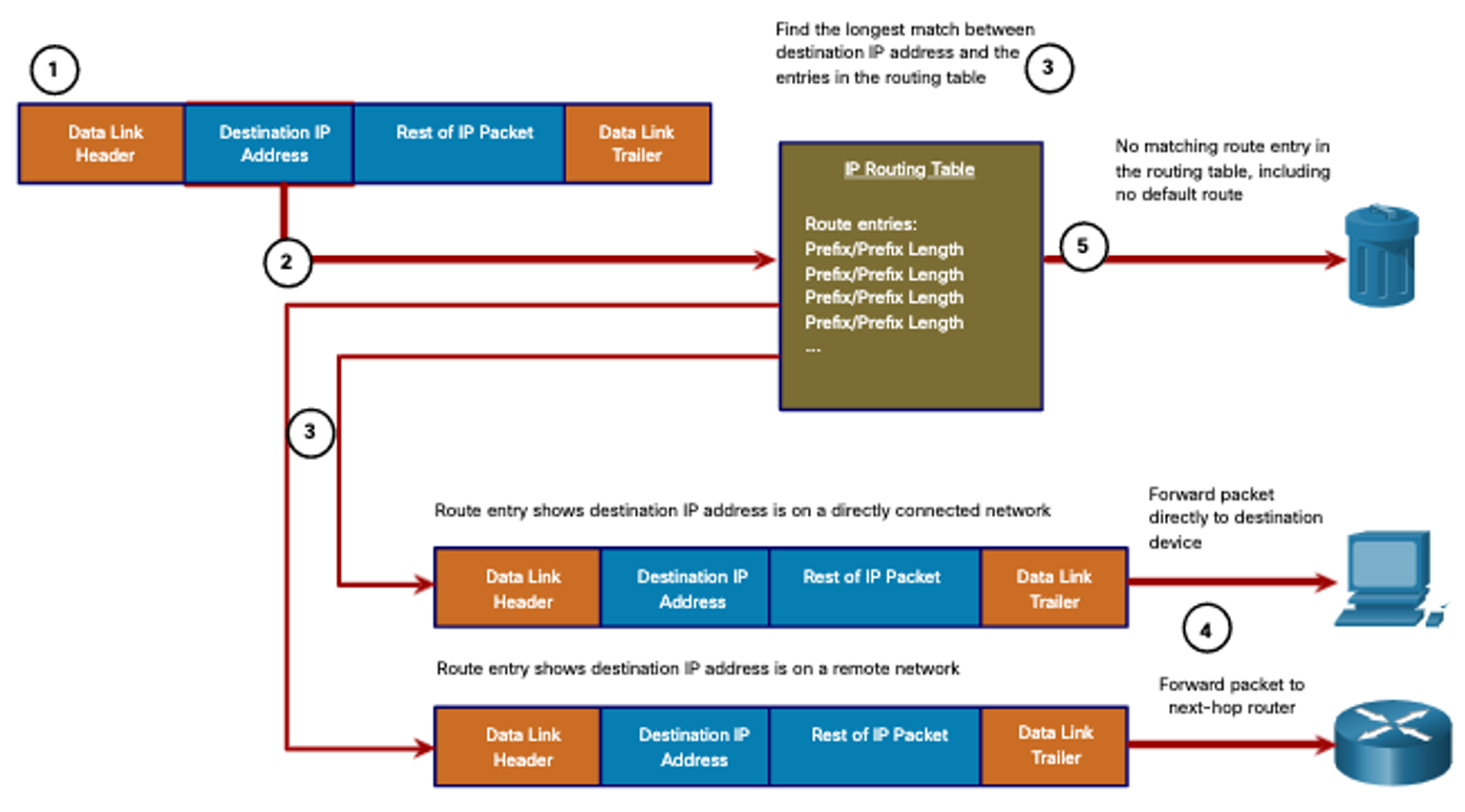 After a router has determined the best path, it could do the following: Forward the Packet to a Device on a Directly Connected Network
- If the route entry indicates that the egress interface is a directly connected network, the packet can be forwarded directly to the destination device. Typically this is an Ethernet LAN.
- To encapsulate the packet in the Ethernet frame, the router needs to determine the destination MAC address associated with the destination IP address of the packet. The process varies based on whether the packet is an IPv4 or IPv6 packet.
After a router has determined the best path, it could do the following: Forward the Packet to a Next-Hop Router
- If the route entry indicates that the destination IP address is on a remote network, meaning a device on network that is not directly connected. The packet must be forwarded to the next-hop router. The next-hop address is indicated in the route entry.
- If the forwarding router and the next-hop router are on an Ethernet network, a similar process (ARP and ICMPv6 Neighbor Discovery) will occur for determining the destination MAC address of the packet as described previously. The difference is that the router will search for the IP address of the next-hop router in its ARP table or neighbor cache, instead of the destination IP address of the packet.
Note: This process will vary for other types of Layer 2 networks. After a router has determined the best path, it could do the following: Drop the Packet – No Match in Routing Table
- If there is no match between the destination IP address and a prefix in the routing table, and if there is no default route, the packet will be dropped.
End-to-End Packet Forwarding
The primary responsibility of the packet forwarding function is to encapsulate packets in the appropriate data link frame type for the outgoing interface. For example, the data link frame format for a serial link could be Point-to-Point (PPP) protocol, High-Level Data Link Control (HDLC) protocol, or some other Layer 2 protocol.
Packet Forwarding Mechanisms
The primary responsibility of the packet forwarding function is to encapsulate packets in the appropriate data link frame type for the outgoing interface. The more efficiently a router can perform this task, the faster packets can be forwarded by the router. Routers support the following three packet forwarding mechanisms:
- Process switching
- Fast switching
- Cisco Express Forwarding (CEF)
Process Switching: An older packet forwarding mechanism still available for Cisco routers. When a packet arrives on an interface, it is forwarded to the control plane where the CPU matches the destination address with an entry in its routing table, and then determines the exit interface and forwards the packet. It is important to understand that the router does this for every packet, even if the destination is the same for a stream of packets. 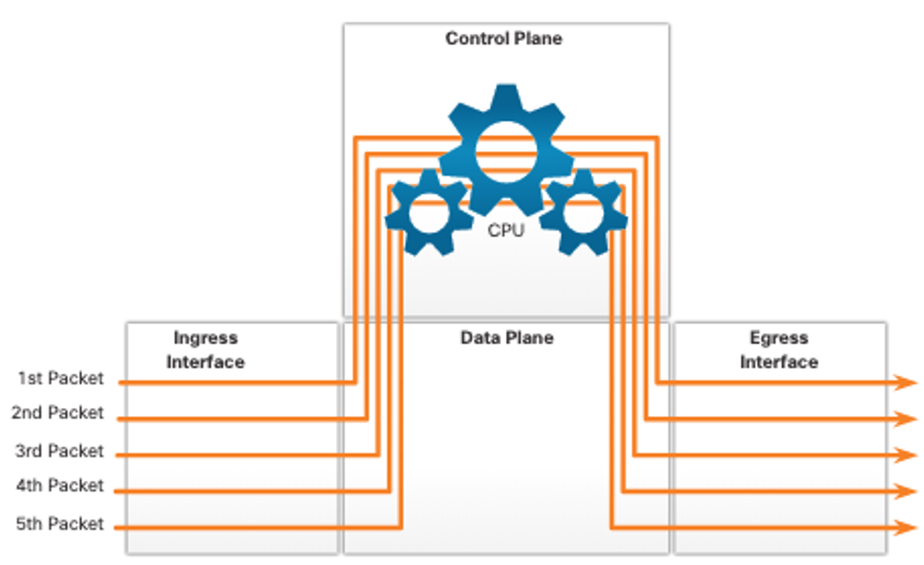 Fast Switching: Another, older packet forwarding mechanism which was the successor to process switching. Fast switching uses a fast-switching cache to store next-hop information. When a packet arrives on an interface, it is forwarded to the control plane where the CPU searches for a match in the fast-switching cache. If it is not there, it is process-switched and forwarded to the exit interface. The flow information for the packet is then stored in the fast-switching cache. If another packet going to the same destination arrives on an interface, the next-hop information in the cache is re-used without CPU intervention.
 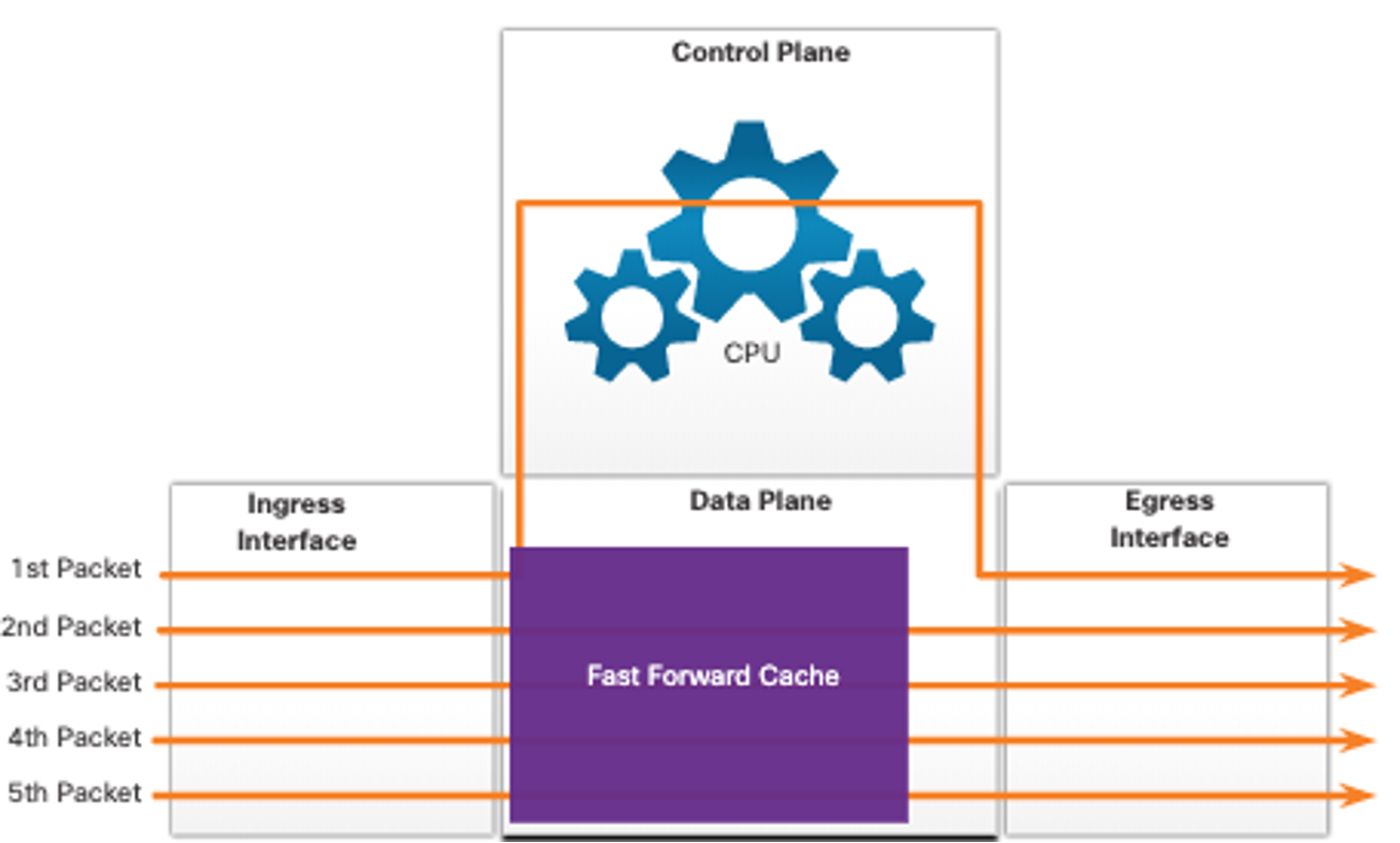 Cisco Express Forwarding (CEF): The most recent and default Cisco IOS packet-forwarding mechanism. CEF builds a Forwarding Information Base (FIB), and an adjacency table. The table entries are not packet-triggered like fast switching but change-triggered, such as when something changes in the network topology. When a network has converged, the FIB and adjacency tables contain all the information that a router would have to consider when forwarding a packet.
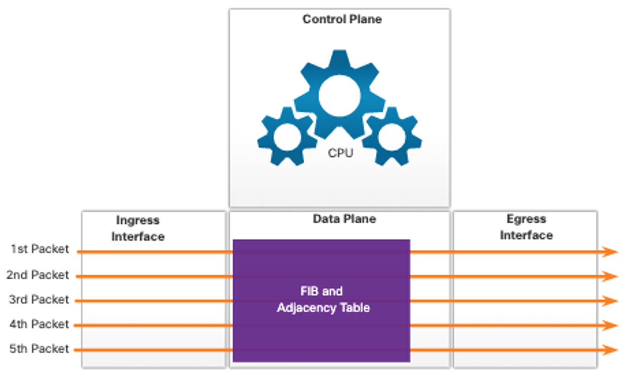
14.3 Basic Router Configuration Review
Topology
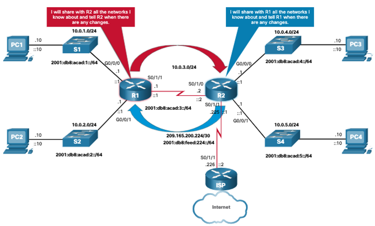
The topology in the figure will be used for configuration and verification examples. It will also be used in the next topic to discuss the IP routing table. 
Configuration Commands
Router> enable

Router# configure terminal

Enter configuration commands, one per line. End with CNTL/Z.

Router(config)# hostname R1

R1(config)# enable secret class

R1(config)# line console 0

R1(config-line)# logging synchronous

R1(config-line)# password cisco

R1(config-line)# login

R1(config-line)# exit

R1(config)# line vty 0 4

R1(config-line)# password cisco

R1(config-line)# login

R1(config-line)# transport input ssh telnet R1(config-line)# exit

R1(config)# service password-encryption R1(config)# banner motd #

Enter TEXT message. End with a new line and the # *********************************************** WARNING: Unauthorized access is prohibited! ***********************************************

#

R1(config)# ipv6 unicast-routing

R1(config)# interface gigabitethernet 0/0/0

R1(config-if)# description Link to LAN 1

R1(config-if)# ip address 10.0.1.1 255.255.255.0

R1(config-if)# ipv6 address 2001:db8:acad:1::1/64

R1(config-if)# ipv6 address fe80::1:a link-local R1(config-if)# no shutdown

R1(config-if)# exit

R1(config)# interface gigabitethernet 0/0/1

R1(config-if)# description Link to LAN 2

R1(config-if)# ip address 10.0.2.1 255.255.255.0 R1(config-if)# ipv6 address 2001:db8:acad:2::1/64 R1(config-if)# ipv6 address fe80::1:b link-local R1(config-if)# no shutdown

R1(config-if)# exit

R1(config)# interface serial 0/1/1

R1(config-if)# description Link to R2

R1(config-if)# ip address 10.0.3.1 255.255.255.0 R1(config-if)# ipv6 address 2001:db8:acad:3::1/64 R1(config-if)# ipv6 address fe80::1:c link-local R1(config-if)# no shutdown

R1(config-if)# exit

R1# copy running-config startup-config

Destination filename [startup-config]?

Building configuration...

[OK]

R1#
Verification Commands
Common verification commands include the following:
- show ip interface brief
- show running-config interface interface-type number
- show interfaces
- show ip interface
- show ip route
- ping
In each case, replace ip with ipv6 for the IPv6 version of the command.
Filter Command Output
Filtering commands can be used to display specific sections of output. To enable the filtering command, enter a pipe (|) character after the show command and then enter a filtering parameter and a filtering expression. The filtering parameters that can be configured after the pipe include:
- section – This displays the entire section that starts with the filtering expression.
- include – This includes all output lines that match the filtering expression.
- exclude – This excludes all output lines that match the filtering expression.
- begin – This displays all the output lines from a certain point, starting with the line that
- matches the filtering expression.
Note: Output filters can be used in combination with any show command.
14.4 IP Routing Table
Route Sources
A routing table contains a list of routes to known networks (prefixes and prefix lengths). The source of this information is derived from the following:
- Directly connected networks
- Static routes
- Dynamic routing protocols
The source for each route in the routing table is identified by a code. Common codes include the following:
- L – Identifies the address assigned to a router interface.
- C – Identifies a directly connected network.
- S – Identifies a static route created to reach a specific network.
- O – Identifies a dynamically learned network from another router using the OSPF routing protocol.
- * – This route is a candidate for a default route.
Routing Table Principles
There are three routing table principles as described in the table. These are issues that are addressed by the proper configuration of dynamic routing protocols or static routes on all the routers between the source and destination devices.
|
Routing Table Principle |
Example |
|
Every router makes its decision alone, based on the information it has in its own routing table. |
•R1 can only forward packets using its own routing table.
•R1 does not know what routes are in the routing tables of other routers (e.g., R2).
|
|
The information in a routing table of one router does not necessarily match the routing table of another router. |
Just because R1 has route in its routing table to a network in the internet via R2, that does not mean that R2 knows about that same network. |
|
Routing information about a path does not provide return routing information. |
R1 receives a packet with the destination IP address of PC1 and the source IP address of PC3. Just because R1 knows to forward the packet out its G0/0/0 interface, doesn’t necessarily mean that it knows how to forward packets originating from PC1 back to the remote network of PC3 |
Routing Table Entries
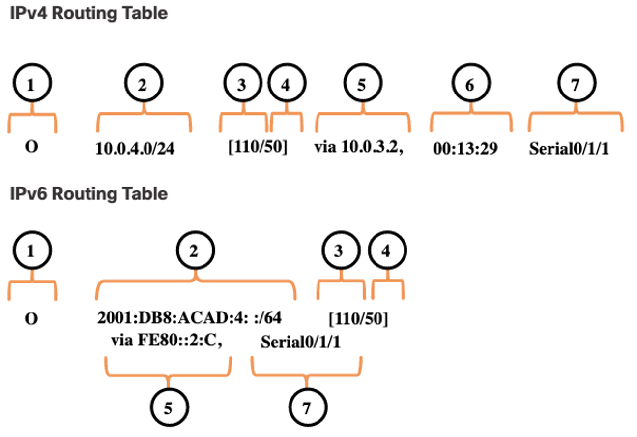
In the figure, the numbers identify the following information:
- Route source – This identifies how the route was learned.
- Destination network (prefix and prefix length) – This identifies the address of the remote network.
- Administrative distance – This identifies the trustworthiness of the route source. Lower values indicate preferred route source.
- Metric – This identifies the value assigned to reach the remote network. Lower values indicate preferred routes.
- Next-hop – This identifies the IP address of the next router to which the packet would be forwarded.
- Route timestamp – This identifies how much time has passed since the route was learned. Exit interface – This identifies the egress interface to use for outgoing packets to reach their final destination.
 Note: The prefix length of the destination network specifies the minimum number of far-left bits that must match between the IP address of the packet and the destination network (prefix) for this route to be used.
Directly Connected Networks
To learn about any remote networks, the router must have at least one active interface configured with an IP address and subnet mask (prefix length). This is known as a directly connected network or a directly connected route. Routers add a directly connected route to its routing table when an interface is configured with an IP address and is activated.
- A directly connected network is denoted by a status code of C in the routing table. The route contains a network prefix and prefix length.
- The routing table also contains a local route for each of its directly connected networks, indicated by the status code of L.
- For IPv4 local routes the prefix length is /32 and for IPv6 local routes the prefix length is /128. This means the destination IP address of the packet must match all the bits in the local route for this route to be a match. The purpose of the local route is to efficiently determine when it receives a packet for the interface instead of a packet that needs to be forwarded.
Static Routes
After directly connected interfaces are configured and added to the routing table, static or dynamic routing can be implemented for accessing remote networks. Static routes are manually configured. They define an explicit path between two networking devices. They are not automatically updated and must be manually reconfigured if the network topology changes. Static routing has three primary uses:
- It provides ease of routing table maintenance in smaller networks that are not expected to grow significantly.
- It uses a single default route to represent a path to any network that does not have a more specific match with another route in the routing table. Default routes are used to send traffic to any destination beyond the next upstream router.
- It routes to and from stub networks. A stub network is a network accessed by a single route, and the router has only one neighbor.
Static Routes in the IP Routing Table
The topology in the figure is simplified to show only one LAN attached to each router. The figure shows IPv4 and IPv6 static routes configured on R1 to reach the 10.0.4.0/24 and 2001:db8:acad:4::/64 networks on R2. 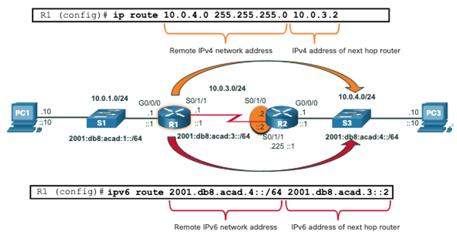
Dynamic Routing Protocols
Dynamic routing protocols are used by routers to automatically share information about the reachability and status of remote networks. Dynamic routing protocols perform several activities, including network discovery and maintaining routing tables.
Dynamic Routes in the Routing Table
OSPF is now being used in our sample topology to dynamically learn all the networks connected to R1 and R2. The routing table entries use the status code of O to indicate the route was learned by the OSPF routing protocol. Both entries also include the IP address of the next-hop router, via ip-address. Note: IPv6 routing protocols use the link-local address of the next-hop router. Note: OSPF routing configuration for IPv4 and IPv6 is beyond the scope of this course. 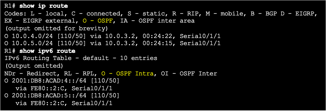
Default Route
The default route specifies a next-hop router to use when the routing table does not contain a specific route that matches the destination IP address. A default route can be either a static route or learned automatically from a dynamic routing protocol. A default route has an IPv4 route entry of 0.0.0.0/0 or an IPv6 route entry of ::/0. This means that zero or no bits need to match between the destination IP address and the default route. 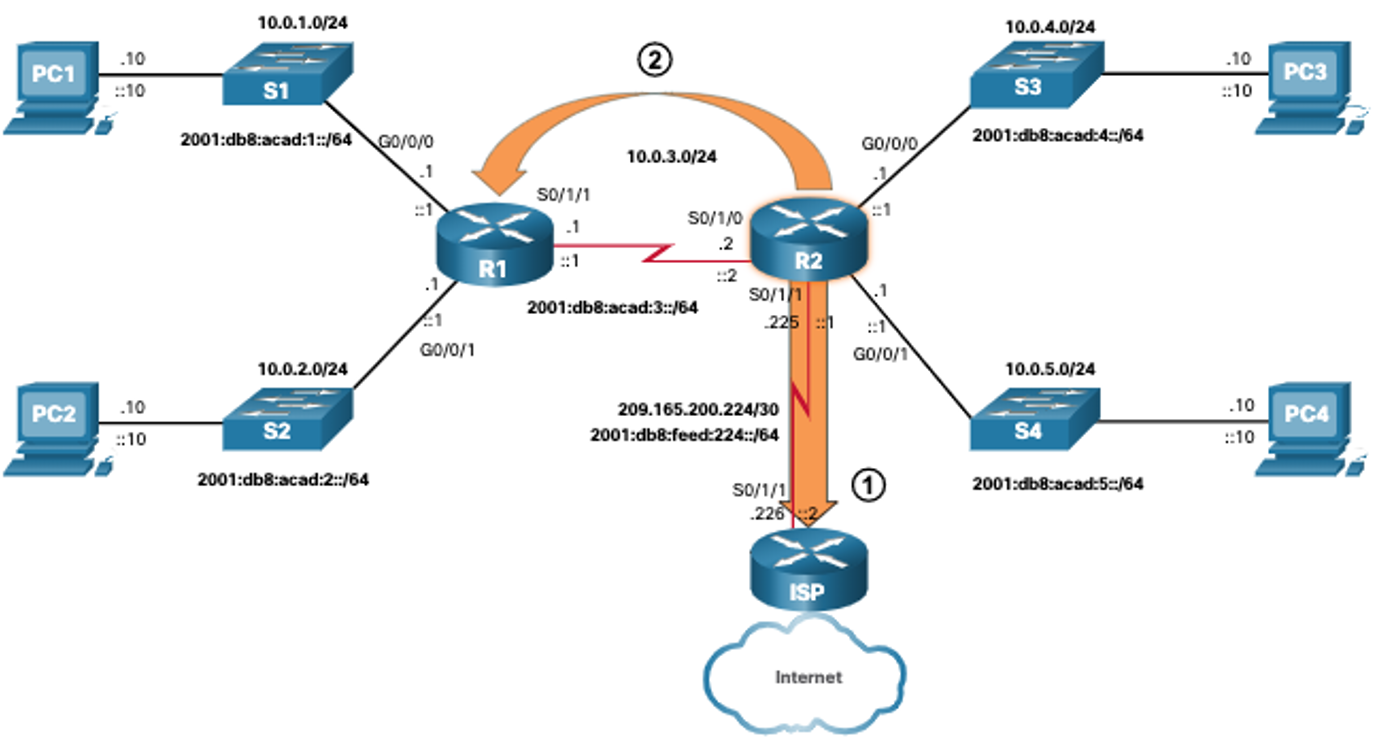
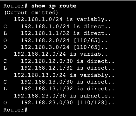
Structure of an IPv4 Routing Table
IPv4 was standardized using the now obsolete classful addressing architecture. The IPv4 routing table is organized using this same classful structure. Although the lookup process no longer uses classes, the structure of the IPv4 routing table still retains in this format. An indented entry is known as a child route. A route entry is indented if it is the subnet of a classful address (class A, B or C network). Directly connected networks will always be indented (child routes) because the local address of the interface is always entered in the routing table as a /32. The child route will include the route source and all the forwarding information such as the next-hop address. The classful network address of this subnet will be shown above the route entry, less indented, and without a source code. That route is known as a parent route.
- An indented entry is known as a child route. A route entry is indented if it is the subnet of a classful address (class A, B or C network).
- Directly connected networks will always be indented (child routes) because the local address of the interface is always entered in the routing table as a /32.
- The child route will include the route source and all the forwarding information such as the next-hop address.
- The classful network address of this subnet will be shown above the route entry, less indented, and without a source code. That route is known as a parent route.
IP Routing TableStructure of an IPv6 Routing Table
The concept of classful addressing was never part of IPv6, so the structure of an IPv6 routing table is very straight forward. Every IPv6 route entry is formatted and aligned the same way. 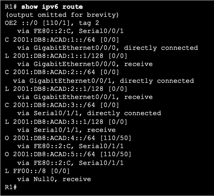
Administrative Distance
A route entry for a specific network address (prefix and prefix length) can only appear once in the routing table. However, it is possible that the routing table learns about the same network address from more than one routing source. Except for very specific circumstances, only one dynamic routing protocol should be implemented on a router. Each routing protocol may decide on a different path to reach the destination based on the metric of that routing protocol. This raises a few questions, such as the following:
- How does the router know which source to use?
- Which route should it install in the routing table?
Cisco IOS uses what is known as the administrative distance (AD) to determine the route to install into the IP routing table. The AD represents the “trustworthiness” of the route. The lower the AD, the more trustworthy the route source. The table lists various routing protocols and their associated ADs.
| Route Source | Administrative Distance |
|---|---|
| Directly connected | 0 |
| Static route | 1 |
| EIGRP summary route | 5 |
| External BGP | 20 |
| Internal EIGRP | 90 |
| OSPF | 110 |
| IS-IS | 115 |
| RIP | 120 |
| External EIGRP | 170 |
| Internal BGP | 200 |
14.5 Static and Dynamic Routing
Static or Dynamic?
Static and dynamic routing are not mutually exclusive. Rather, most networks use a combination of dynamic routing protocols and static routes. Static routes are commonly used in the following scenarios:
- As a default route forwarding packets to a service provider
- For routes outside the routing domain and not learned by the dynamic routing protocol
- When the network administrator wants to explicitly define the path for a specific network
- For routing between stub networks
Static routes are useful for smaller networks with only one path to an outside network. They also provide security in a larger network for certain types of traffic, or links to other networks that need more control. Dynamic routing protocols are implemented in any type of network consisting of more than just a few routers. Dynamic routing protocols are scalable and automatically determine better routes if there is a change in the topology. Dynamic routing protocols are commonly used in the following scenarios:
- In networks consisting of more than just a few routers
- When a change in the network topology requires the network to automatically determine another path
- For scalability. As the network grows, the dynamic routing protocol automatically learns about any new networks.
The table shows a comparison of some the differences between dynamic and static routing.
| Feature | Dynamic Routing | Static Routing |
|---|---|---|
| Configuration complexity | Increases with network size | Independent of network size |
| Topology changes | Automatically adapts to topology changes | Administrator intervention required |
| Scalability | Suitable for simple to complex network topologies | Suitable for simple topologies |
| Security | Security must be configured | Security is inherent |
| Resource Usage | Uses CPU, memory, and link bandwidth | No additional resources needed |
| Path Predictability | Route depends on topology and routing protocol used | Explicitly defined by the administrator |
Dynamic Routing Evolution
Dynamic routing protocols have been used in networks since the late 1980s. One of the first routing protocols was RIP. RIPv1 was released in 1988, but some of the basic algorithms within the protocol were used on the Advanced Research Projects Agency Network (ARPANET) as early as 1969. As networks evolved and became more complex, new routing protocols emerged. 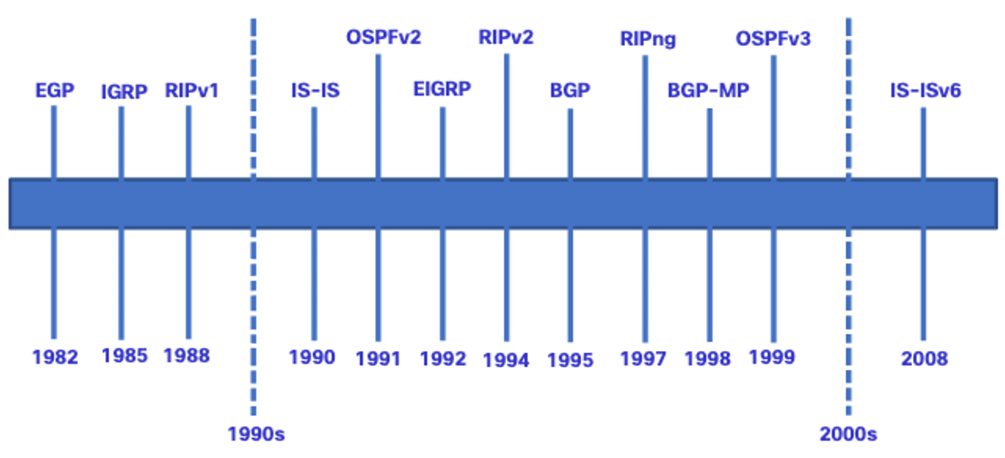 The table classifies the current routing protocols. Interior Gateway Protocols (IGPs) are routing protocols used to exchange routing information within a routing domain administered by a single organization. There is only one EGP and it is BGP. BGP is used to exchange routing information between different organizations, known as autonomous systems (AS). BGP is used by ISPs to route packets over the internet. Distance vector, link-state, and path vector routing protocols refer to the type of routing algorithm used to determine best path.
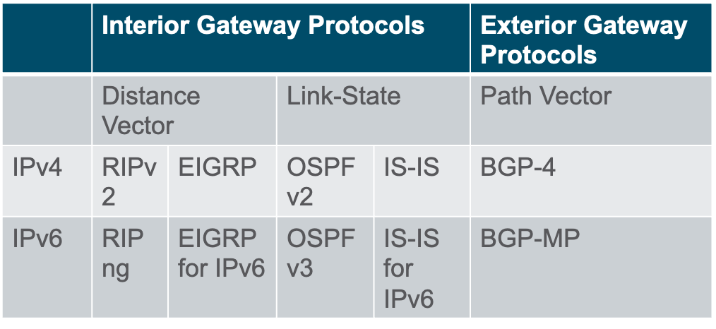
Dynamic Routing Protocol Concepts
A routing protocol is a set of processes, algorithms, and messages that are used to exchange routing information and populate the routing table with the choice of best paths. The purpose of dynamic routing protocols includes the following:
- Discovery of remote networks
- Maintaining up-to-date routing information
- Choosing the best path to destination networks
- Ability to find a new best path if the current path is no longer available
The main components of dynamic routing protocols include the following:
- Data structures – Routing protocols typically use tables or databases for their operations. This information is kept in RAM.
- Routing protocol messages – Routing protocols use various types of messages to discover neighboring routers, exchange routing information, and other tasks to learn and maintain accurate information about the network.
- Algorithm – An algorithm is a finite list of steps used to accomplish a task. Routing protocols use algorithms for facilitating routing information and for the best path determination.
Routing protocols determine the best path, or route, to each network. That route is then offered to the routing table. The route will be installed in the routing table if there is not another routing source with a lower AD.
Best Path
The best path is selected by a routing protocol based on the value or metric it uses to determine the distance to reach a network. A metric is the quantitative value used to measure the distance to a given network. The best path to a network is the path with the lowest metric. Dynamic routing protocols typically use their own rules and metrics to build and update routing tables. The following table lists common dynamic protocols and their metrics.
| Routing Protocol | Metric | Description |
|---|---|---|
| Routing Information Protocol (RIP) | Hop count | Each router along a path adds a hop to the hop count. A maximum of 15 hops allowed. |
| Open Shortest Path First (OSPF) | Cost | Based on the cumulative bandwidth from source to destination. Faster links are assigned lower costs compared to slower (higher cost) links. |
| Enhanced Interior Gateway Routing Protocol (EIGRP) | Calculated metric | Based on the slowest bandwidth and delay values. It could also include load and reliability into the metric calculation. |
Load Balancing
When a router has two or more paths to a destination with equal cost metrics, then the router forwards the packets using both paths equally. This is called equal cost load balancing.
- The routing table contains the single destination network, but has multiple exit interfaces, one for each equal cost path. The router forwards packets using the multiple exit interfaces listed in the routing table.
- If configured correctly, load balancing can increase the effectiveness and performance of the network.
- Equal cost load balancing is implemented automatically by dynamic routing protocols. It is enabled with static routes when there are multiple static routes to the same destination network using different next-hop routers.
Note: Only EIGRP supports unequal cost load balancing.