About Lesson
Configure Switch Ports
Configure switch ports to meet network requirements.
Duplex Communication
- Full-duplex communication increases bandwidth efficiency by allowing both ends of a connection to transmit and receive data simultaneously. This is also known as bidirectional communication and it requires microsegmentation.
- A microsegmented LAN is created when a switch port has only one device connected and is operating in full-duplex mode. There is no collision domain associated with a switch port operating in full-duplex mode.
- Unlike full-duplex communication, half-duplex communication is unidirectional. Half-duplex communication creates performance issues because data can flow in only one direction at a time, often resulting in collisions.
- Gigabit Ethernet and 10 Gb NICs require full-duplex connections to operate. In full-duplex mode, the collision detection circuit on the NIC is disabled. Full-duplex offers 100 percent efficiency in both directions (transmitting and receiving). This results in a doubling of the potential use of the stated bandwidth.
Configure Switch Ports at the Physical Layer
- Switch ports can be manually configured with specific duplex and speed settings. The respective interface configuration commands are duplex and speed.
- The default setting for both duplex and speed for switch ports on Cisco Catalyst 2960 and 3560 switches is auto. The 10/100/1000 ports operate in either half- or full-duplex mode when they are set to 10 or 100 Mbps and operate only in full-duplex mode when it is set to 1000 Mbps (1 Gbps).
- Autonegotiation is useful when the speed and duplex settings of the device connecting to the port are unknown or may change. When connecting to known devices such as servers, dedicated workstations, or network devices, a best practice is to manually set the speed and duplex settings.
- When troubleshooting switch port issues, it is important that the duplex and speed settings are checked.
Note: Mismatched settings for the duplex mode and speed of switch ports can cause connectivity issues. Autonegotiation failure creates mismatched settings.
- All fiber-optic ports, such as 1000BASE-SX ports, operate only at one preset speed and are always full-duplex

| Task | Command |
|---|---|
| Enter global configuration mode. | S1# configure terminal |
| Enter interface configuration mode. | S1(config)# interface FastEthernet 0/1 |
| Configure the interface duplex. | S1(config-if)# duplex full |
| Configure the interface speed. | S1(config-if)# speed 100 |
| Return to the privileged EXEC mode. | S1(config-if)# end |
| Save the running config to the startup config. | S1# copy running-config startup-config |
Auto-MDIX
- When automatic medium-dependent interface crossover (auto-MDIX) is enabled, the switch interface automatically detects the required cable connection type (straight-through or crossover) and configures the connection appropriately.
- When connecting to switches without the auto-MDIX feature, straight-through cables must be used to connect to devices such as servers, workstations, or routers. Crossover cables must be used to connect to other switches or repeaters.
- With auto-MDIX enabled, either type of cable can be used to connect to other devices, and the interface automatically adjusts to communicate successfully.
- On newer Cisco switches, the mdix auto interface configuration mode command enables the feature. When using auto-MDIX on an interface, the interface speed and duplex must be set to auto so that the feature operates correctly.
- Note: The auto-MDIX feature is enabled by default on Catalyst 2960 and Catalyst 3560 switches but is not available on the older Catalyst 2950 and Catalyst 3550 switches.
- To examine the auto-MDIX setting for a specific interface, use the show controllers ethernet-controller command with the phy keyword. To limit the output to lines referencing auto-MDIX, use the include Auto-MDIX filter.
Switch Verification Commands
| Task | IOS Command |
|---|---|
| Display interface status and configuration. | S1# show interfaces [interface-id] |
| Display current startup configuration. | S1# show startup-config |
| Display current running configuration. | S1# show running-config |
| Display information about flash file system. | S1# show flash |
| Display system hardware and software status. | S1# show version |
| Display history of command entered. | S1# show history |
| Display IP information about an interface. | S1# show ip interface [interface-id] OR S1# show ipv6 interface [interface-id] |
| Display the MAC address table. | S1# show mac-address-table OR S1# show mac address-table |
Verify Switch Port Configuration
- The show running-config command can be used to verify that the switch has been correctly configured. From the sample abbreviated output on S1, some important information is shown in the figure:
- Fast Ethernet 0/18 interface configured with the management VLAN 99
- VLAN 99 configured with an IPv4 address of 172.17.99.11 255.255.255.0
- Default gateway set to 172.17.99.1

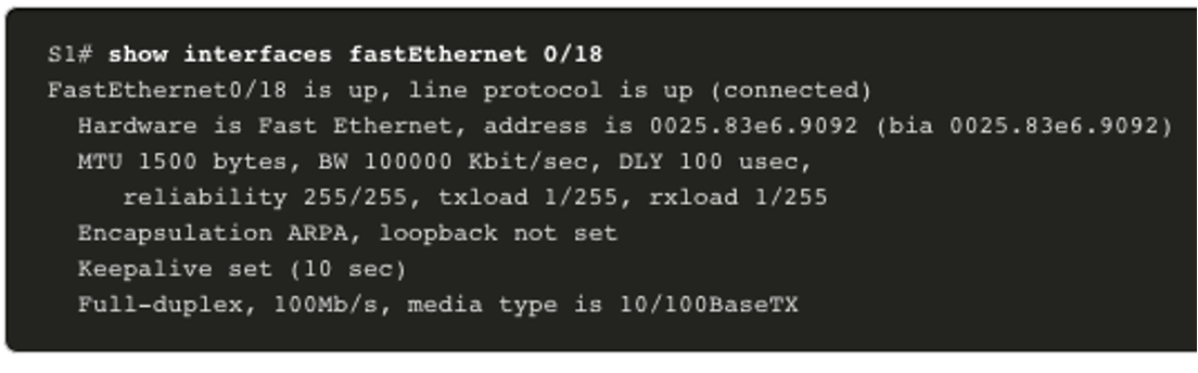
- The show interfaces command is another commonly used command, which displays status and statistics information on the network interfaces of the switch. The show interfaces command is frequently used when configuring and monitoring network devices.
- The first line of the output for the show interfaces fastEthernet 0/18 command indicates that the FastEthernet 0/18 interface is up/up, meaning that it is operational. Further down, the output shows that the duplex is full and the speed is 100 Mbps.
Network Access Layer Issues
- The output from the show interfaces command is useful for detecting common media issues.
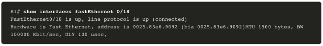
- One of the most important parts of this output is the display of the line and data link protocol status, as shown in the example.
- The first parameter (FastEthernet0/18 is up) refers to the hardware layer and indicates whether the interface is receiving a carrier detect signal.
- The second parameter (line protocol is up) refers to the data link layer and indicates whether the data link layer protocol keepalives are being received. Based on the output of the show interfaces command, possible problems can be fixed as follows:
-
- If the interface is up and the line protocol is down, a problem exists. There could be an encapsulation type mismatch, the interface on the other end could be error-disabled, or there could be a hardware problem.
- If the line protocol and the interface are both down, a cable is not attached, or some other interface problem exists.
- For example, in a back-to-back connection, the other end of the connection may be administratively down. If the interface is administratively down, it has been manually disabled (the shutdown command has been issued) in the active configuration.
- The show interfaces command output displays counters and statistics for the FastEthernet0/18 interface, as shown here:
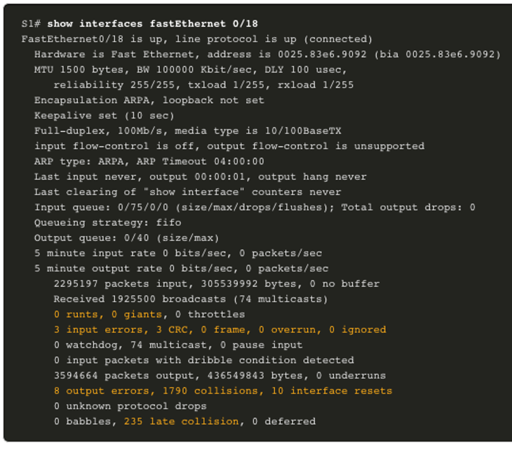
- Some media errors are not severe enough to cause the circuit to fail but do cause network performance issues. The table explains some of these common errors which can be detected using the show interfaces command.
| Error Type | Description |
|---|---|
| Input Errors | Total number of errors. It includes runts, giants, no buffer, CRC, frame, overrun, and ignored counts. |
| Runts | Packets that are discarded because they are smaller than the minimum packet size for the medium. For instance, any Ethernet packet that is less than 64 bytes is considered a runt. |
| Giants | Packets that are discarded because they exceed the maximum packet size for the medium. For example, any Ethernet packet that is greater than 1,518 bytes is considered a giant. |
| CRC | CRC errors are generated when the calculated checksum is not the same as the checksum received. |
| Output Errors | Sum of all errors that prevented the final transmission of datagrams out of the interface that is being examined. |
| Collisions | Number of messages retransmitted because of an Ethernet collision. |
| Late Collisions | A collision that occurs after 512 bits of the frame have been transmitted. |
Interface Input and Output Errors
- “Input errors” is the sum of all errors in datagrams that were received on the interface being examined. This includes runts, giants, CRC, no buffer, frame, overrun, and ignored counts. The reported input errors from the show interfaces command include the following:
- Runt Frames – Ethernet frames that are shorter than the 64-byte minimum allowed length are called runts. Malfunctioning NICs are the usual cause of excessive runt frames, but they can also be caused by collisions.
- Giants – Ethernet frames that are larger than the maximum allowed size are called giants.
- CRC errors – On Ethernet and serial interfaces, CRC errors usually indicate a media or cable error. Common causes include electrical interference, loose or damaged connections, or incorrect cabling. If you see many CRC errors, there is too much noise on the link and you should inspect the cable. You should also search for and eliminate noise sources.
- “Output errors” is the sum of all errors that prevented the final transmission of datagrams out the interface that is being examined. The reported output errors from the show interfaces command include the following:
- Collisions – Collisions in half-duplex operations are normal. However, you should never see collisions on an interface configured for full-duplex communication.
- Late collisions – A late collision refers to a collision that occurs after 512 bits of the frame have been transmitted. Excessive cable lengths are the most common cause of late collisions.
- Another common cause is duplex misconfiguration.
Troubleshooting Network Access Layer Issues
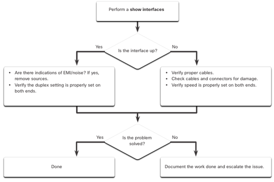
To troubleshoot scenarios involving no connection, or a bad connection, between a switch and another device, follow the general process shown in the figure.
Other related topics
| Topic Title | Topic Objective |
|---|---|
| Configure a Switch with Initial Settings | Configure initial settings on a Cisco switch. |
| Configure Switch Ports | Configure switch ports to meet network requirements. |
| Secure Remote Access | Configure secure management access on a switch. |
| Basic Router Configuration | Configure basic settings on a router to route between two directly-connected networks, using CLI. |
| Verify Directly Connected Networks | Verify connectivity between two networks that are directly connected to a router. |
Other useful information
Join the conversation