Network Functions Virtualization
This section describes the NFV architecture and its application to an enterprise network.
- Network functions virtualization (NFV) is an architectural framework created by the European Telecommunications Standards Institute (ETSI) that defines standards to decouple network functions from proprietary hardware-based appliances and have them run in software on standard x86 servers.
- It also defines how to manage and orchestrate the network functions.
- Network function (NF) refers to the function performed by a physical appliance, such as a firewall or a router function.
NFV Benefits
Some of the benefits of NFV are similar to the benefits of server virtualization and cloud environments:
- Reduced capital expenditure (capex) and operational expenditure (opex) through reduced equipment costs and efficiencies in space, power, and cooling
- Faster time to market (TTM) because VMs and containers are easier to deploy than hardware
- Improved return on investment (ROI) from new services
- Ability to scale up/out and down/in capacity on demand (elasticity)
- Openness to the virtual appliance market and pure software networking vendors
- Opportunities to test and deploy new innovative services virtually and with lower risk
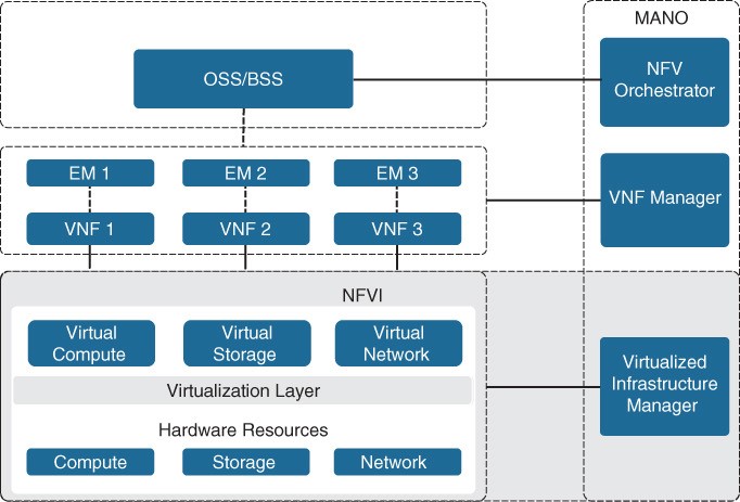
Figure 27-7 ETSI NFV Architectural Framework demand (elasticity) NFV infrastructure (NFVI) is all the hardware and software components that comprise the platform environment in which virtual network functions (VNFs) are deployed.
Virtual Network Functions – VNF
A virtual network function (VNF) is the virtual or software version of an NF, and it typically runs on a hypervisor as a VM. VNFs are commonly used for Layer 4 through Layer 7 functions, such as those provided by load balancers (LBs) and application delivery controllers (ADCs), firewalls, intrusion detection systems (IDSs), and WAN optimization appliances. However, they are not limited to Layer 4 through Layer 7 functions; they can also perform lower-level Layer 2 and Layer 3 functions, such as those provided by routers and switches. Some examples of Cisco VNFs include the following:
- Cisco Cloud Services Router 1000V (CSR 1000V)
- Cisco Cloud Services Platform 2100 (CSP 2100)
- Cisco Integrated Services Virtual Router (ISRv)
- Cisco NextGen Firewall Virtual Appliance (NGFWv)
- Cisco Adaptive Security Virtual Appliance (ASAv)
Virtualized Infrastructure Manager
- The NFVI Virtualized Infrastructure Manager (VIM) is responsible for managing and controlling the NFVI hardware resources (compute, storage, and network) and the virtualized resources.
- It is also responsible for the collection of performance measurements and fault information.
- It performs lifecycle management (setup, maintenance, and teardown) of all NFVI resources as well as VNF service chaining. Service chaining is connecting VNFs together to provide an NFV service or solution, as illustrated in Figure 27-8.
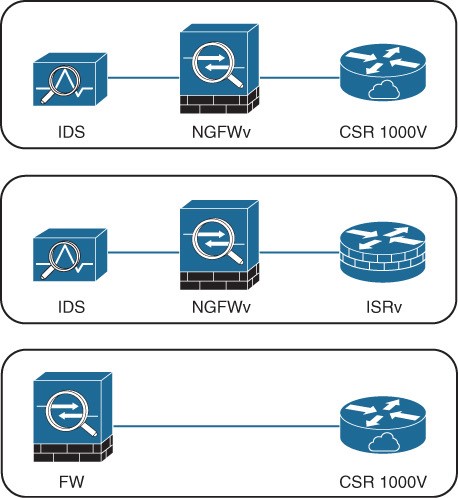 Figure 27-8 Service Chaining
Element Managers/Management and Orchestration
Element managers (EMs), also known as element management systems (EMSs), are responsible for the functional management of VNFs. They perform fault, configuration, accounting, performance, and security (FCAPS) functions for VNFs. A single EM can manage one or multiple VNFs, and an EM can also be a VNF. The NFV orchestrator is responsible for creating, maintaining, and tearing down VNF network services.
- If multiple VNFs are part of a network service, the NFV orchestrator enables the creation of an end-to-end network service over multiple VNFs.
- The VNF manager manages the lifecycle of one or multiple VNFs as well as FCAPS for the virtual components of a VNF.
- The NFV orchestrator and VNF manager together are known as NFV management and orchestration (MANO). Refer back to Figure 27-7.
OSS/BSS
Operations Support System (OSS) is a platform typically operated by service providers (SPs) and large enterprise networks to support all their network systems and services.
- The OSS can assist them in maintaining network inventory, provisioning new services, configuring network devices, and resolving network issues.
- For SPs, OSS typically operates in tandem with BSS to improve the overall customer experience.
- BSS is a combination of product management, customer management, revenue management (billing), and order management systems that are used to run the SP’s business operations. Refer back to Figure 27-7.
VNF Performance
In NFV solutions, the data traffic has two different patterns: north–south and east– west.
- North–south traffic comes into the hosting server through a physical NIC (pNIC) and is sent to a VNF. Then it is sent from the VNF back out to the physical wire through the pNIC.
- East–west traffic comes into the hosting server through a pNIC and is sent to a VNF. From there, it could be sent to another VNF (service chained) and possibly service chained to more VNFs and then sent back out to the physical wire through a pNIC.
- There can also be combinations of the two, where a VNF uses a north–south traffic pattern for user data and an east–west traffic pattern to send traffic to a VNF that is just collecting statistics or that is just being used for logs or storage.
Terminology
The most popular technologies to achieve optimal VNF performance and throughput are described in this section, but before describing them, it is important to understand the following terminology:
| Term | Description |
| Input/output (I/O) | The communication between a computing system (such as a server) and the outside world. Input is the data received by the computing system, and output is the data sent from it. |
| I/O device | A peripheral device such as a mouse, keyboard, monitor, or network interface card (NIC). |
| Interrupt request (IRQ) | A hardware signal sent to the CPU by an I/O device (such as a NIC) to notify the CPU when it has data to transfer. When the CPU receives the interrupt (IRQ), it saves its current state, temporarily stops what it’s doing, and runs an interrupt handler routine associated to the device. |
| Device driver | A computer program that controls an I/O device and allows the CPU to communicate with the I/O device. A NIC is an example of an I/O device that requires a driver to operate and interface with the CPU. |
| Direct memory access (DMA) | A memory access method that allows an I/O device to send or receive data directly to or from the main memory, bypassing the CPU, to speed up overall computer operations. |
| Kernel and user space: | The core part of an operating system (OS) and a memory area where applications and their associated libraries reside. The kernel (“core” in German) is a program that is the central (core) part of an OS. User space is where applications and their associated libraries reside. |
Packet Flow Virtualized Environment
- In a virtual environment, there are pNICs and virtual NICs (vNICs) and a hypervisor with a virtual switch in between them.
- The hypervisor and the virtual switch are responsible for taking the data from the pNIC and sending it to the vNIC of the VM/VNF and finally to the application.
- The addition of the virtual layer introduces additional packet processing and virtualization overhead, which creates bottlenecks and reduces I/O packet throughput.
The packet flow for a virtualized system with an Open vSwitch (OVS) architecture is illustrated in Figure 27-10. 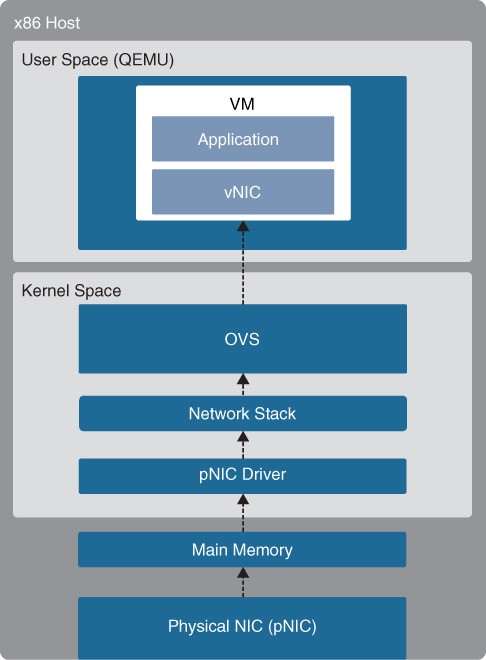 Figure 27-10 x86 Host with OVS
Packet Flow Steps for Packets Received by pNIC
The high-level packet flow steps for packets received by the pNIC and delivered to the application in the VM are as follows:
- Data traffic is received by the pNIC and placed into an Rx queue (ring buffers) within the pNIC.
- The pNIC sends the packet and a packet descriptor to the main memory buffer through DMA. The packet descriptor includes only the memory location and size of the packet.
- The pNIC sends an IRQ to the CPU.
- The CPU transfers control to the pNIC driver, which services the IRQ, receives the packet, and moves it into the network stack, where it eventually arrives in a socket and is placed into a socket receive buffer.
- The packet data is copied from the socket receive buffer to the OVS virtual switch.
- OVS processes the packet and forwards it to the VM. This entails switching the packet between the kernel and user space, which is expensive in terms of CPU cycles.
- The packet arrives at the virtual NIC (vNIC) of the VM and is placed into an Rx queue.
- The vNIC sends the packet and a packet descriptor to the virtual memory buffer through DMA.
- The vNIC sends an IRQ to the vCPU.
- The vCPU transfers control to the vNIC driver, which services the IRQ, receives the packet, and moves it into the network stack, where it eventually arrives in a socket and is placed into a socket receive buffer.
- The packet data is copied and sent to the application in the VM.
OVS-DPDK
- To overcome the performance impact on throughput due to interrupts, OVS was enhanced with the Data Plane Development Kit (DPDK) libraries, operating entirely in user space. The DPDK Poll Mode Driver (PMD) in OVS polls for data that comes into the pNIC and processes it, bypassing the network stack and the need to send an interrupt to the CPU when a packet is received (bypassing the kernel).
- To be able to do this, DPDK PMD requires one or more CPU cores dedicated to polling and handling the incoming data. When the packet is in OVS, it’s already in user space, and it can then be switched directly to the appropriate VNF, resulting in huge performance benefits.
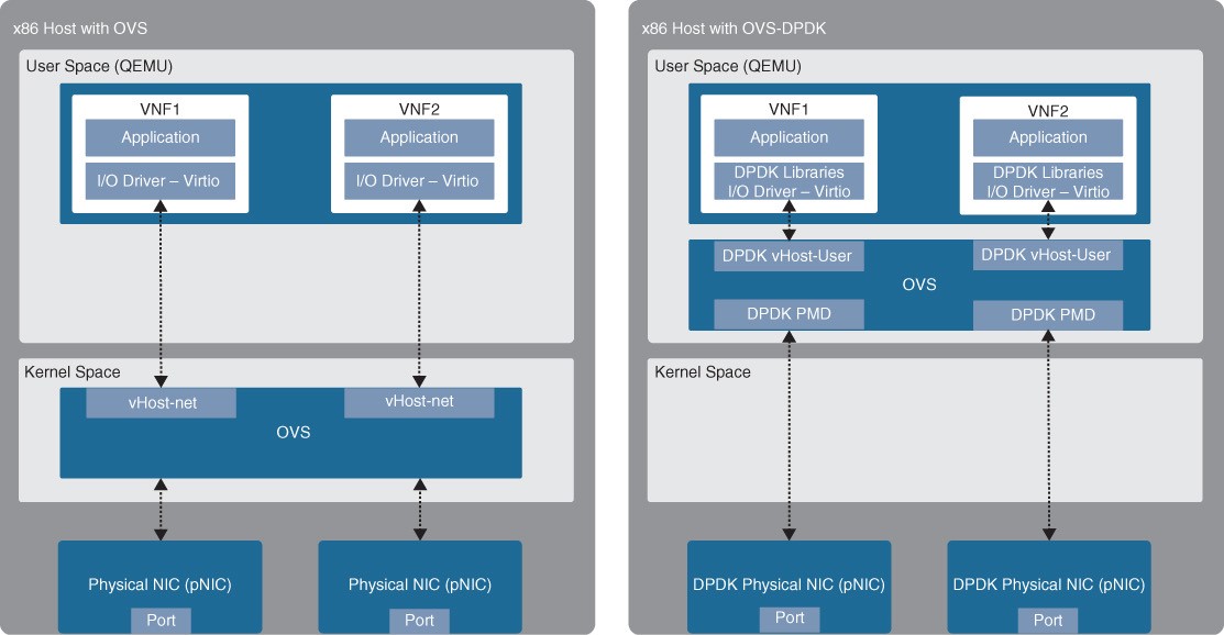
- Figure 27-11 Standard OVS and OVS-DPDK Figure 27-11 illustrates an x86 host with a standard OVS compared to an x86 host with an OVS with DPDK.
PCI Passthrough
PCI Passthrough allows VNFs to have direct access to physical PCI devices, which appear and behave as if they were physically attached to the VNF. PCI passthrough offers many performance advantages including:
- Exclusive one-to-one mapping
- Bypassed hypervisor
- Direct access to I/O resources
- Reduced CPU utilization
- Reduced system latency
- Increased I/O throughput
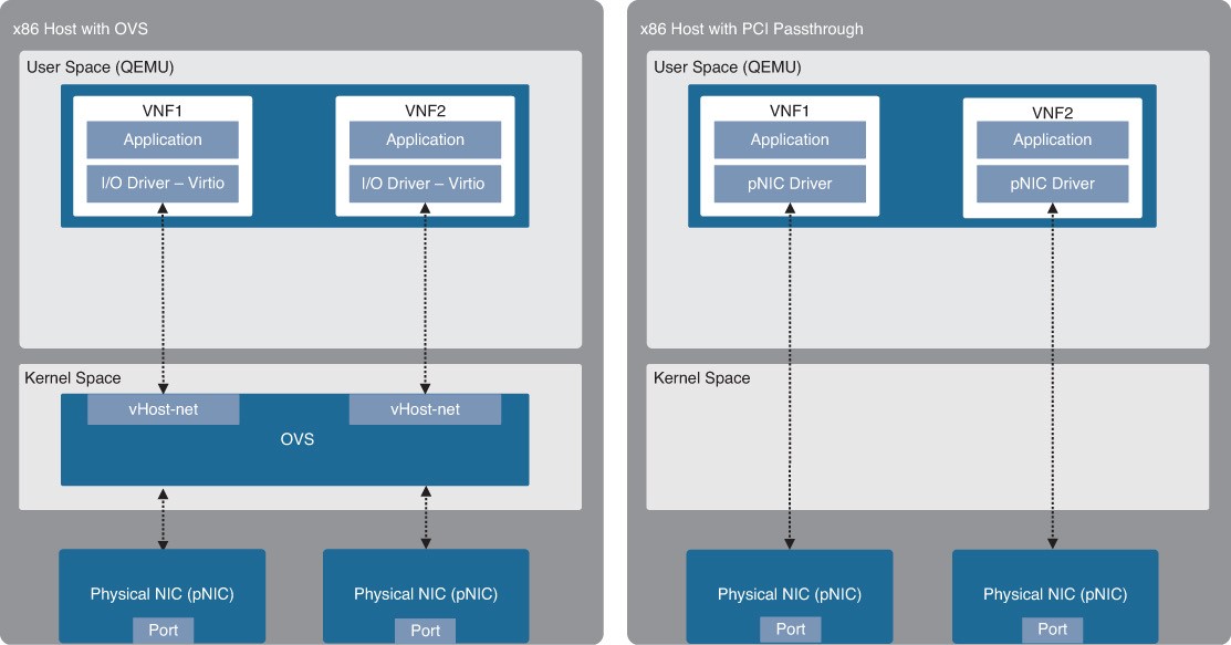
- Figure 27-12 Standard OVS and PCI Passthrough Figure 27-12 illustrates an x86 host with a standard OVS and an x86 host with PCI passthrough.
SR-IOV
SR-IOV is an enhancement to PCI passthrough that allows multiple VNFs to share the same pNIC. SRIOV emulates multiple PCIe devices on a single PCIe device (such as a pNIC). In SR-IOV, the emulated PCIe devices are called virtual functions (VFs), and the physical PCIe devices are called physical functions (PFs). The VNFs have direct access to the VFs, using PCI passthrough technology. An SR-IOV-enabled pNIC supports two different modes for switching traffic between VNFs:
- Virtual Ethernet Bridge (VEB) – Traffic between VNFs attached to the same pNIC is hardware switched directly by the pNIC.
- Virtual Ethernet Port Aggregator (VEPA) Traffic between VNFs attached to the same pNIC is switched by an external switch.
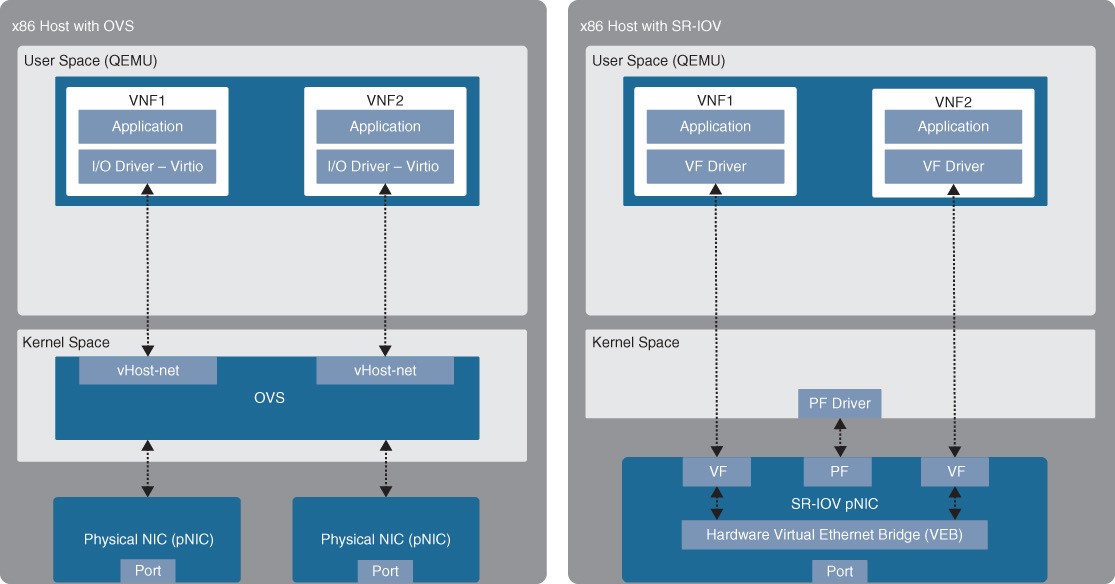
- Figure 27-13 Standard OVS and SR-IOV Figure 27-13 illustrates an x86 host with a standard OVS compared to an x86 host with SR-IOV.
Cisco Enterprise Network Functions Virtualization (ENFV)
The Cisco ENFV solution is based on the ETSI NFV architectural framework. It reduces the operational complexity of enterprise branch environments by running the required networking functions as virtual networking functions (VNFs) on standard x86-based hosts. The Cisco ENFV solution provides the following benefits:
- Reduces the number of physical devices to be managed at the branch, resulting in efficiencies in space, power, maintenance, and cooling
- Reduces the need for truck rolls and technician site visits to perform hardware installations or upgrades
- Offers operational simplicity that allows it to roll out new services, critical updates, VNFs, and branch locations in minutes
- Centralizes management through Cisco DNA Center, which greatly simplifies designing, provisioning, updating, managing, and troubleshooting network services and VNFs
- Enhances network operations flexibility by taking full advantage of virtualization techniques such as virtual machine moves, snapshots, and upgrades
- Supports Cisco SD-WAN cEdge and vEdge virtual router onboarding • Supports third-party VNFs
Cisco ENFV Solution Architecture
Cisco ENFV delivers a virtualized solution for network and application services for branch offices. It consists of four main components that are based on the ETSI NFV architectural framework:
- Management and Orchestration (MANO)
- VNFs
- Network Functions Virtualization Infrastructure Software (NFVIS):
- Hardware resources
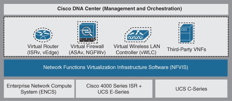
- Figure 27-14 Enterprise NFV Solution Main Components Figure 27-14 illustrates the main components of Cisco’s Enterprise NFV solution.
Management and Orchestration
Cisco DNA Center provides centralized policies, which enables consistent network policies across the enterprise branch offices. Centralized policies are created by building network profiles. Multiple network profiles can be created, each with specific design requirements and virtual services. Once they are created, branch sites are then assigned to network profiles that match the branch requirements. Network profiles include information such as the following:
- Configuration for LAN and WAN virtual interfaces
- Services or VNFs to be used, such as a firewall or WAN optimizer, and their requirements, such as service chaining parameters, CPU, and memory requirements
- Device configuration required for the VNFs, which can be customized by using custom configuration templates created through a template editor tool
Virtual Network Functions and Applications
The Cisco Enterprise NFV solution provides an environment for the virtualization of both network functions and applications in the enterprise branch. Both Cisco and third-party VNFs can be onboarded onto the solution. Applications running in a Linux server or Windows server environment can also be instantiated on top of NFVIS and can be supported by DNA Center. Cisco-supported VNFs include the following:
- Cisco Integrated Services Virtual Router (ISRv) for virtual routing
- Cisco Adaptive Security Virtual Appliance (ASAv) for a virtual firewall
- Cisco Firepower Next-Generation Firewall virtual (NGFWv) for integrated firewall and intrusion detection and prevention
- Viptela vEdge
- cEdge
- Cisco virtual Wide Area Application Services (vWAAS) for virtualized WAN optimization
- Cisco virtual wireless LAN controllers (vWLCs) for virtualized wireless LAN controllers
Third-party VNFs include ThousandEyes, Fortinet, PaloAlto, InfoVista, CTERA, Windows Server, Linux Server
Network Function Virtualization Infrastructure Software (NFVIS)
- NFVIS is based on standard Linux packaged with additional functions for virtualization, VNF lifecycle management, monitoring, device programmability, and hardware acceleration.
- The components and functionality delivered by NFVIS are illustrated in Figure 27-16.
- The next slides describe all of these functions.
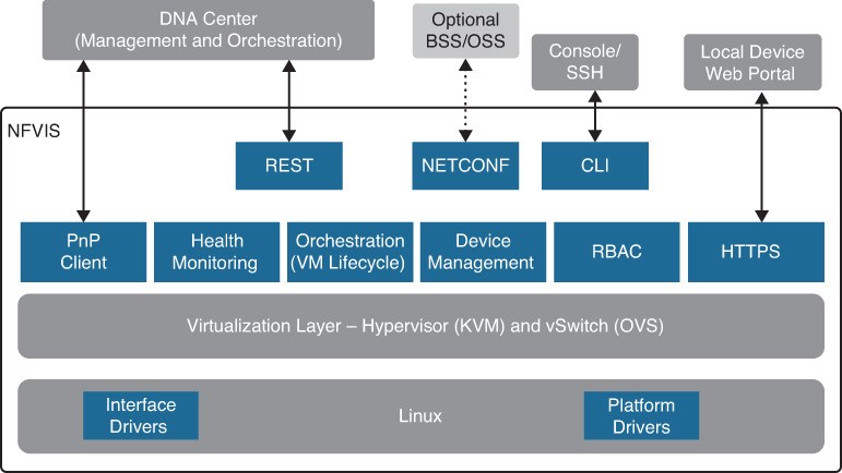
- Figure 27-16 Enterprise NFV Solution Main Components
NFVIS Component Descriptions
- Linux – Linux drives the underlying hardware platforms and hosts the virtualization layer for VNFs, virtual switching API interfaces, interface drivers, platform drivers, and management.
- Hypervisor – The hypervisor for virtualization is based on Kernel-based Virtual Machine (KVM) and includes Quick Emulator (QEMU), Libvirt, and other associated processes.
- Virtual switch (vSwitch) – The vSwitch is Open vSwitch (OVS), and it enables communication between different VNFs (service chaining) and to the outside world.
- VM lifecycle management – NFVIS provides the VIM functionality as specified in the NFV architectural framework through the NFVIS embedded Elastic Services Controller (ESC) Lite. ESC-Lite supports dynamic bringup of VNFs—creating and deleting VNFs and adding CPU cores, memory, and storage.
- Plug and Play client – The Plug and Play client communicates with a Plug and Play server running in Cisco DNA Center and is provisioned with the right host configuration.
NFVIS Component Descriptions (Cont.)
- Orchestration – REST, CLI, HTTPS, and NETCONF/YANG communication models are supported for orchestration and management.
- HTTPS web server – The web server can enable connectivity into NFVIS through HTTPS to a local device’s web portal. From this portal, it is possible to upload VNF packages, implement full lifecycle management, turn services up and down, connect to VNF consoles, and monitor critical parameters, without the need for complex commands.
- Device management – Tools are packaged into NFVIS to support device management, including a resource manager to get information on the number of CPU cores allocated to VMs and the CPU cores that are already used by the VMs.
- Role-based access control (RBAC) – Users accessing the platform are authenticated using RBAC.