
Enterprise Network Architecture Options
the different options available for deploying an enterprise campus architecture based on the hierarchical LAN design model.
- Two-tier design (collapsed core)
- Three-tier design
- L2 access layer (STP based)
- L3 access layer (routed access)
- Simplified campus design
- Software-Defined Access (SD-Access)
Two-tier design (Collapsed Core)
- Smaller campus networks may have multiple departments spread across multiple floors within a building. In these environments, a core layer may not be needed, and collapsing the core function into the distribution layer can be a cost-effective solution (as no core layer means no core layer devices) that requires no sacrifice of most of the benefits of the three-tier hierarchical model.
- Prior to selecting a two-tier collapsed core and distribution layers, future scale, expansion, and manageability factors need to be considered.
Switches at the Core/Distribution layer provide two separate functions:
- connectivity to the WAN, Data Center, internet, and network services edge blocks
- LAN aggregation to the end-user access layer switches
Figure 22-7 Two-Tier/Collapsed Core Design LAN controllers (WLCs).
- The WAN Edge block connects to remote data centers, remote branches, or other campus networks or for connectivity to cloud providers. The Data Center/Server Room block is where business-critical servers are placed.
- The Internet Edge block is used for regular internet access, e-commerce, connection to remote branches, remote VPN access and non-dedicated cloud provider connections.
- The Network Services block is where devices providing network services reside, such as wireless
Three-Tier Design
Three-tier designs separate the core and distribution layers and are recommended when more than two pairs of distribution switches are required. Multiple pairs of distribution switches are typically required for the following reasons:
- When implementing a network for a large enterprise campus composed of multiple buildings, where each building requires a dedicated distribution layer.
- When the density of WAN routers, internet edge devices, data center servers, and network services are growing to the point where they can affect network performance and throughput.
- When geographic dispersion of the LAN access switches across many buildings in a larger campus facility would require more fiber-optic interconnects back to a single collapsed core.
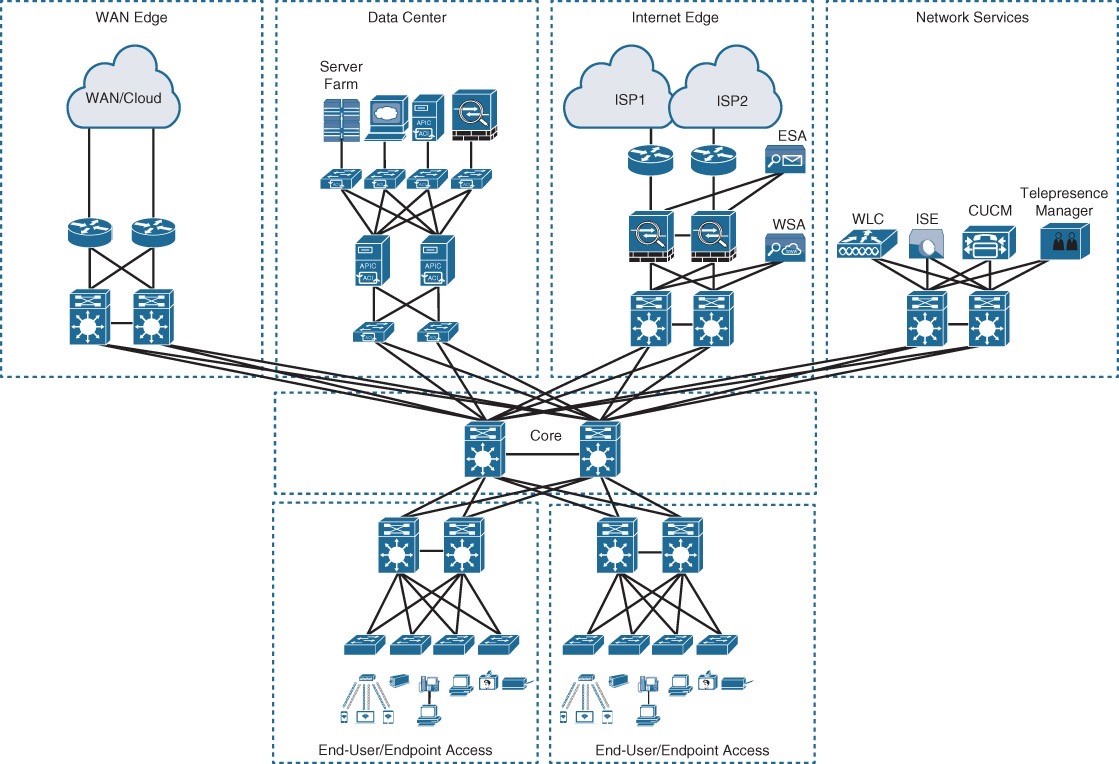
Figure 22-8 Three-Tier Design center.
- In Figure 22-8, the building blocks or places in the network (PINs) are each using the hierarchical design model.
- Each block is deployed with a pair of distribution switches connected to the core.
- The hierarchical LAN design is more appropriate for north–south traffic flows, such as endpoints communicating with the WAN edge, data center, Internet, or network services blocks.
- The data center block is using the newer leaf–spine design, an alternative to the threetier design when traffic is predominantly east–west between servers within the data
Layer 2 Access Layer (STP Based)
- Traditional LAN designs use a Layer 2 access layer and a Layer 3 distribution layer.
- The distribution layer is the Layer 3 IP gateway for access layer hosts.
- Whenever possible, it is recommended to restrict a VLAN to a single access layer switch to eliminate topology loops.
- Restricting a VLAN to a single switch provides a loop-free design, but at the cost of network flexibility because all hosts within a VLAN are restricted to a single access switch.
- Some organizations require that the same Layer 2 VLAN be extended to multiple access layer switches to accommodate an application or a service.
- The looped design causes STP to block links, which reduces the bandwidth from the rest of the network and can cause slower network convergence.
Layer 2 Access Layer (STP Based) – Topology Design
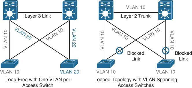
Figure 22-9 Loop-Free Topology and Looped Topology Figure 22-9 illustrates a loop-free topology where a VLAN is constrained to a single switch, as well as a looped topology where a VLAN spans multiple access switches. The looped design causes STP to block links.
Layer 2 Access Layer (STP Based) – High Availability
- First-hop redundancy protocols (FHRPs) provide hosts with a consistent MAC address and gateway IP address for each configured VLAN. The distribution layer should have a pair of standalone switches configured with a FHRP.
- Hot Standby Router Protocol (HSRP) and Virtual Router Redundancy Protocol (VRRP) are the most common first-hop redundancy protocols.
- The downside to these protocols is that they only allow hosts to send data out the active FHRP router through a single access uplink.
- This leaves one of the access layer-to-distribution layer uplinks unutilized unless manual configuration of the distribution layer is performed.
- Gateway Load Balancing Protocol (GLBP) provides greater uplink utilization for access layer-to-distribution layer traffic by load balancing the load from hosts across multiple uplinks.
- The downside is that it works only on loop-free topologies.
Layer 3 Access Layer (Routed Access)
Routed access is an alternative configuration in which Layer 3 is extended all the way to the access layer switches. In this design, access layer switches act as full Layer 3 routed nodes (providing both Layer 2 and Layer 3 switching), and the access-todistribution Layer 2 uplink trunks are replaced with Layer 3 point-to-point routed links. Consequently, the Layer 2/Layer 3 demarcation point is moved from the distribution switch to the access switch, as illustrated in Figure 22-10. 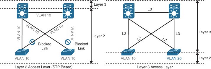 Figure 22-10 Layer 2 Access Layer and Layer 3 Access Layer
Layer 3 Access Layer (Routed Access)
The routed access-to-distribution block design advantages over the Layer 2 access layer design:
- No first-hop redundancy protocol required – It eliminates the need for first-hop redundancy protocols such as HSRP and VRRP.
- No STP required – Because there are no Layer 2 links to block, this design eliminates the need for STP.
- Increased uplink utilization – Both uplinks from access to distribution can be used, increasing the effective bandwidth available to the end users and endpoints connected to the access layer switches.
- Easier troubleshooting – It offers common end-to-end troubleshooting tools (such as ping and traceroute).
- Faster convergence – It uses fast-converging routing protocols such as Enhanced Interior Gateway Routing Protocol (EIGRP) and Open Shortest Path First (OSPF).
Simplified Campus Design
Relies on switch clustering such as a virtual switching system (VSS) and stacking technologies such as StackWise, in which multiple physical switches act as a single logical switch. Clustering and stacking technologies can be applied to any of the campus building blocks to simplify them even further. Using this design offers the following advantages:
- Simplified design – By using the single logical distribution layer design, there are fewer boxes to manage, which reduces the amount of time spent on ongoing provisioning and maintenance.
- No first-hop redundancy protocol required – It eliminates the need for first-hop redundancy protocols such as HSRP and VRRP because the default IP gateway is on a single logical interface.
- Reduced STP dependence – Because EtherChannel is used, it eliminates the need for STP for a Layer 2 access design. However, STP is still required as a failsafe in case multiple access switches are interconnected.
Simplified Campus Design advantages:
- Increased uplink utilization – With EtherChannel, all uplinks from access to distribution can be used, increasing the effective bandwidth available to the end users and endpoints connected to the access layer switches.
- Easier troubleshooting – The topology of the network from the distribution layer to the access layer is logically a hub-and-spoke topology, which reduces the complexity of the design and troubleshooting.
- Faster convergence – With EtherChannel, all links are in forwarding state, and this significantly optimizes the convergence time following a node or link failure event. Provides fast sub-second failover between links in an uplink bundle.
- Distributed VLANs – With this design, VLANs can span multiple access switches without the need to block any links.
The simplified campus design is loop free, highly available, flexible, resilient, and easy to manage. Figure 22-11 illustrates how the network can be simplified by introducing VSS and StackWise into the design.
 Figure 22-11 Simplified Campus Design with VSS and StackWise
Simplified Campus Design
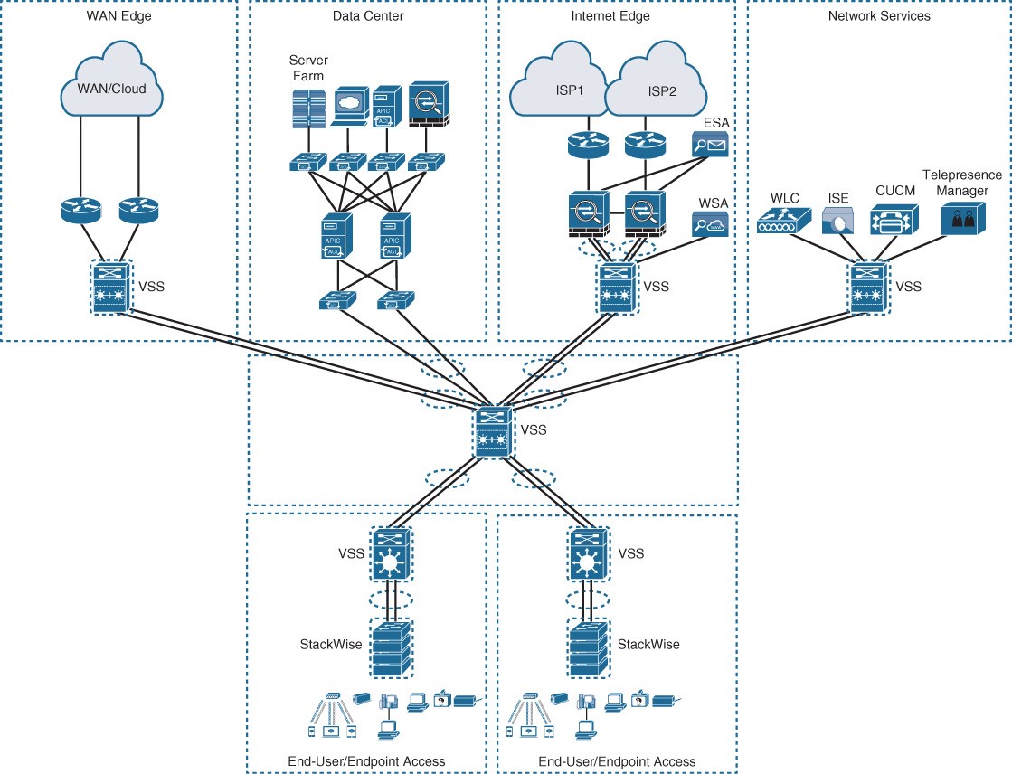
Figure 22-12 Applying VSS and StackWise in a Campus Network
Using the simplified campus design approach across all the campus blocks (when possible) can provide an optimized architecture that is easy to manage, resilient, and more flexible, with higher aggregated uplink bandwidth capacity.
SD-Access Design
SD-Access – Industry’s first intent-based networking solution for the enterprise
- Built on the principles of the Cisco Digital Network Architecture (DNA) • A combination of the campus fabric design and Cisco DNA or DNAC).
- Adds fabric capabilities to the enterprise network through automation
- Provides automated end-to-end segmentation to separate user, device, and application traffic without requiring a network redesign
- Fabric capabilities provide services such as host mobility and enhanced security in addition to the normal switching and routing capabilities.