Software-Defined Access (SD-Access)
This section defines the benefits of SD-Access over traditional campus networks as well as the components and features of the Cisco SD-Access solution, including the nodes, fabric control plane, and data plane.
- A fabric network is an overlay network (virtual network) built over an underlay network (physical network) using overlay tunneling technologies such as VXLAN. Fabric networks improve upon traditional physical networks by enabling host mobility, network automation, network virtualization, and segmentation. They are more manageable, flexible, secure (by means of encryption), and scalable than traditional networks.
- Manual network configuration changes are slow and can lead to misconfigurations that cause service disruptions on the network. The situation is exacerbated in a constantly changing environment where more users, endpoints, and applications are being added.
- The increase in users and endpoints makes configuring user credentials and maintaining a consistent policy across the network very complex.
SD Access Features
With SD-Access, an evolved campus network can be built that addresses the needs of existing campus networks by leveraging the following capabilities, features, and functionalities:
- Network automation – SD-Access replaces manual network device configurations with network device management through a single point of automation, orchestration, and management of network functions through the use of Cisco DNA Center.
- Network assurance and analytics – SD-Access enables proactive prediction of networkrelated and security-related risks by using telemetry to improve the performance of the network, endpoints, and applications, including encrypted traffic.
- Host mobility – SD-Access provides host mobility for both wired and wireless clients.
- Identity services – Cisco Identity Services Engine (ISE) identifies users and devices connecting to the network and provides the contextual information required for users and devices to implement security policies for network access control and network segmentation.
SD Access Features (Cont.)
- Policy enforcement – Traditional access control lists (ACLs) can be difficult to deploy, maintain, and scale because they rely on IP addresses and subnets. Creating access and application policies based on group-based policies using Security Group Access Control Lists (SGACLs) provides a much simpler and more scalable form of policy enforcement based on identity instead of an IP address.
- Secure segmentation – With SD-Access it is easier to segment the network to support guest, corporate, facilities, and IoT-enabled infrastructure.
- Network virtualization – SD-Access makes it possible to leverage a single physical infrastructure to support multiple virtual routing and forwarding (VRF) instances, referred to as virtual networks (VNs), each with a distinct set of access policies.
What is SD Access?
SD-Access has two main components:
- Cisco Campus fabric solution – The campus fabric is a Cisco-validated fabric overlay solution that includes all of the features and protocols (control plane, data plane, management plane, and policy plane) to operate the network infrastructure.
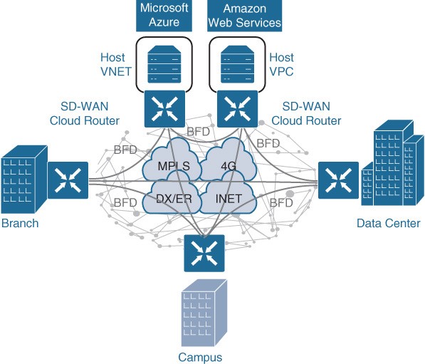
- Cisco DNA Center – When the campus fabric solution is managed via the Cisco DNA Center, the solution is considered to be SD-Access, as illustrated in Figure 23-1.
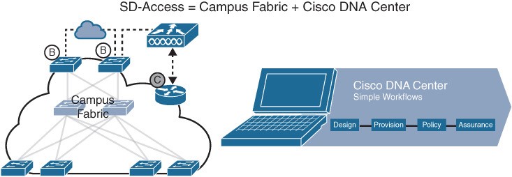
Figure 23-1 SD-Access Solution
What is SD Access Architecture
Cisco SD-Access is based on existing hardware and software technologies. What makes Cisco SD-Access special is how these technologies are integrated and managed together. The Cisco SD-Access fabric architecture can be divided into four basic layers, as illustrated in Figure 23-2.
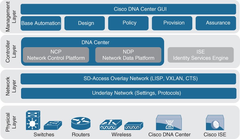
Figure 23-2 Cisco SD-Access Architecture
Physical Layer
While Cisco SD-Access is designed for user simplicity, abstraction, and virtual environments, everything runs on top of physical network devices (switches, routers, servers, wireless LAN controllers (WLCs), and wireless access points (APs). Cisco access layer switches that do not actively participate in the SD-Access fabric but that are part of it because of automation are referred to as SD-Access extension nodes. The following are the physical layer devices of the SD-WAN fabric:
- Cisco switches – Switches provide wired (LAN) access to the fabric. Multiple types of Cisco Catalyst switches are supported, as well as Nexus switches.
- Cisco routers – Routers provide WAN and branch access to the fabric. Multiple types of Cisco ASR 1000, ISR, and CSR routers, including the CSRv and ISRv cloud routers, are supported.
- Cisco wireless – Cisco WLCs and APs provide wireless (WLAN) access to the fabric.
- Cisco controller appliances – Cisco DNA Center and Cisco ISE are the two controller appliances required.
Network Layer
- The network layer consists of the underlay network and the overlay network. These two sublayers work together to deliver data packets to and from the network devices participating in SDAccess. All this network layer information is made available to the controller layer.
- The network underlay is the underlying physical layer, and its sole purpose is to transport data packets between network devices for the SDAccess fabric overlay.
- The overlay network is a virtual (tunneled) network that virtually interconnects all of the network devices forming a fabric of interconnected nodes. It abstracts the inherent complexities and limitations of the underlay network.
Figure 23-3 Underlay and Overlay Networks Figure 23-3 shows a visual representation of the relationship between an overlay network and the network underlay.
Underlay Network
Two models of underlay that are supported are as follows:
- Manual underlay – This type of underlay network is configured and managed manually (such as with a CLI or an API) rather than through Cisco DNA Center. An advantage of the manual underlay is that it allows customization of the network to fit any special design requirements (such as changing the IGP to OSPF). It allows SD-Access to run on the top of a legacy (or third-party) IP-based network.
- Automated underlay – In a fully automated network underlay, all aspects of the underlay network are configured and managed by the Cisco DNA Center LAN Automation feature. The LAN Automation feature creates an IS-IS routed access campus design. It uses the Cisco Network Plug and Play features to deploy both unicast and multicast routing configuration in the underlay to improve traffic delivery efficiency for SD-Access. An automated underlay eliminates misconfigurations and reduces the complexity of the network underlay. It also greatly simplifies and speeds the building of the network underlay. A downside to an automated underlay is that it does not allow manual customization for special design requirements.
Overlay Network (SD-Access Fabric)
The SD-Access fabric is the overlay network, and it provides policy-based network segmentation, host mobility for wired and wireless hosts, and enhanced security beyond the normal switching and routing capabilities of a traditional network. In SD-Access, the fabric overlay is fully automated, regardless of the underlay network model used (manual or automated). It includes all necessary overlay control plane protocols and addressing, as well as all global configurations associated with operation of the SD-Access fabric. There are three basic planes of operation in the SD-Access fabric:
- Control plane, based on Locator/ID Separation Protocol (LISP)
- Data plane, based on Virtual Extensible LAN (VXLAN)
- Policy plane, based on Cisco TrustSec
SD-Access Control Plane
The SD-Access fabric control plane is based on Locator/ID Separation Protocol (LISP).
- LISP is an IETF standard protocol defined in RFC 6830 that is based on a simple endpoint ID (EID) to routing locator (RLOC) mapping system to separate the identity (endpoint IP address) from its current location (network edge/border router IP address).
- LISP dramatically simplifies traditional routing environments by eliminating the need for each router to process every possible IP destination address and route. It does this by moving remote destination information to a centralized mapping database called the LISP map server (MS) (a control plane node in SD-Access), which allows each router to manage only its local routes and query the map system to locate destination EIDs.
- This technology provides many advantages for Cisco SD-Access, such as smaller routing tables, dynamic host mobility for wired and wireless endpoints, address-agnostic mapping (IPv4, IPv6, and/ or MAC), and built-in network segmentation through VRF instances.
SD-Access Fabric Data Plane
SD-Access Fabric Data Plane The tunneling technology used for the fabric data plane is based on Virtual Extensible LAN (VXLAN). VXLAN encapsulation is IP/UDP based, meaning that it can be forwarded by any IP-based network (legacy or third party) and creates the overlay network for the SDAccess fabric. Although LISP is the control plane for the SD-Access fabric, it does not use LISP data
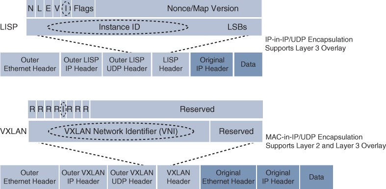
Figure 23-4 LISP and VXLAN Packet Format Comparison encapsulation for the data plane. The differences between the LISP and VXLAN packet formats are illustrated in Figure 23-4.
SD-Access Fabric Plane (Cont.)
The original VXLAN specification was enhanced for SD-Access to support Cisco TrustSec Scalable Group Tags (SGTs). This added new fields to the first 4 bytes of the VXLAN header in order to transport up to 64,000 SGT tags. The new VXLAN format is called VXLAN Group Policy Option (VXLAN-GPO), and it is defined in the IETF draft draft-smith-vxlan-group-policy-05. The new fields in the VXLAN-GPO packet format include the following:
- Group Policy ID – 16-bit identifier that is used to carry the SGT tag.
- Group Based Policy Extension Bit (G Bit) – 1-bit field that, when set to 1, indicates an SGT tag is being carried within the Group Policy ID field and is set to 0 when it is not.
- Don’t Learn Bit (D Bit) – 1-bit field that when set to 1 indicates that the egress virtual tunnel endpoint (VTEP) must not learn the source address of the encapsulated frame.
- Policy Applied Bit (A Bit) – 1-bit field that is only defined as the A bit when the G bit field is set to 1. When the A bit is set to 1, it indicates that the group policy has already been applied to this packet, and further policies must not be applied by network devices. When it is set to 0, group policies must be applied by network devices, and they must set the A bit to 1 after the policy has been applied.
SD-Access Fabric Policy Plane
The fabric policy plane is based on Cisco TrustSec. Cisco TrustSec SGT tags are assigned to authenticated groups of users or end devices. Network policy (for example, ACLs, QoS) is then applied throughout the SD-Access fabric, based on the SGT tag instead of a network address (MAC, IPv4, or IPv6). TrustSec SGT tags provide several advantages for Cisco SD-Access, such as:
- Support for both network-based segmentation using VNs (VRF instances) and group-based segmentation (policies)
- Network address-independent group-based policies based on SGT tags rather than MAC, IPv4, or IPv6 addresses, which reduces complexity
- Dynamic enforcement of group-based policies, regardless of location for both wired and wireless traffic
- Policy constructs over a legacy or third-party network using VXLAN
- Extended policy enforcement to external networks (such as cloud or data center networks) by transporting the tags to Cisco TrustSec-aware devices using SGT Exchange Protocol (SXP)
SD-Access Fabric Roles and Components
The operation of the SD-Access fabric requires multiple different device roles, each with a specific set of responsibilities. Each SDAccess-enabled network device must be configured for one (or more) of the five basic device roles in the fabric overlay:
- Control plane node
- Fabric border node
- Fabric edge node
- Fabric WLAN controller (WLC)
- Intermediate nodes
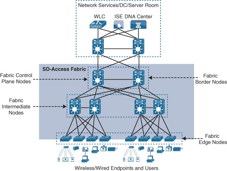
Figure 23-6 SD-Access Fabric Roles Figure 23-6 illustrates the different SD-Access fabric design roles and how nodes in the fabric can play multiple roles. For example, the core layer routers in this figure are acting as fabric border nodes and control plane nodes.
Fabric Edge Nodes
- A fabric edge node provides onboarding and mobility services for wired users and devices (including fabric-enabled WLCs and APs) connected to the fabric. It is a LISP tunnel router (xTR) that also provides the anycast gateway, endpoint authentication, and assignment to overlay host pools (static or DHCP), as well as group-based policy enforcement (for traffic to fabric endpoints).
- A fabric edge first identifies and authenticates wired endpoints (through 802.1x), in order to place them in a host pool (SVI and VRF instance) and scalable group (SGT assignment). It then registers the specific EID host address (that is, MAC, /32 IPv4, or /128 IPv6) with the control plane node.
- A fabric edge provides a single Layer 3 anycast gateway (that is, the same SVI with the same IP address on all fabric edge nodes) for its connected endpoints and also performs the encapsulation and de-encapsulation of host traffic to and from its connected endpoints.
- An edge node must be either a Cisco switch or router operating in the fabric overlay.
Fabric Control Plane Nodes
- A fabric control plane node is a LISP map server/resolver (MS/MR) with enhanced functions for SD-Access, such as fabric wireless and SGT mapping. It maintains a simple host tracking database to map EIDs to RLOCs.
- The control plane (host database) maps all EID locations to the current fabric edge or border node, and it is capable of multiple EID lookup types (IPv4, IPv6, or MAC).
- The control plane receives registrations from fabric edge or border nodes for known EID prefixes from wired endpoints and from fabric mode WLCs for wireless clients. It also resolves lookup requests from fabric edge or border nodes to locate destination EIDs and updates fabric edge nodes and border nodes with wired and wireless client mobility and RLOC information.
- Control plane devices must maintain all endpoint (host) mappings in a fabric. A device with sufficient hardware and software scale for the fabric must be selected for this function.
Fabric Border Nodes
Fabric border nodes are LISP proxy tunnel routers (PxTRs) that connect external Layer 3 networks to the SD-Access fabric and translate reachability and policy information, such as VRF and SGT information, from one domain to another. There are three types of border nodes:
- Internal border (rest of company) – Connects only to the known areas of the organization (for example, WLC, firewall, data center).
- Default border (outside) – Connects only to unknown areas outside the organization. This border node is configured with a default route to reach external unknown networks such as the internet or the public cloud that are not known to the control plane nodes.
- Internal + default border (anywhere) – Connects transit areas as well as known areas of the company. This is basically a border that combines internal and default border functionality into a single node.
Fabric Wireless Controller (WLC)
- A fabric-enabled WLC connects APs and wireless endpoints to the SD-Access fabric. The WLC is external to the fabric and connects to the SDAccess fabric through an internal border node.
- In traditional wireless deployments, the WLC is typically centralized, and all control plane and data plane (wireless client data) traffic needs to be tunneled to the WLC through the Control and Provisioning of Wireless Access Points (CAPWAP) tunnel.
- In SD-Access, the wireless control plane remains centralized, but the data plane is distributed using
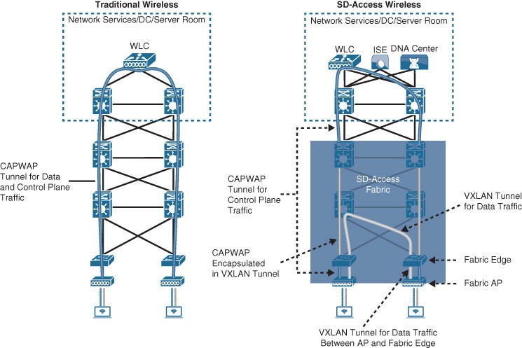
Figure 23-7 Traditional Wireless and SD-Access Wireless Deployments VXLAN directly from the fabric-enabled APs. Figure 23-7 illustrates a traditional wireless deployment compared to an SD-Access wireless deployment.
SD-Access Fabric Concepts
Better understanding the benefits and operation of Cisco SD-Access requires reviewing the following concepts related to how the multiple technologies that are used by the SD-WAN solution operate and interact in SD-Access:
- Virtual network (VN) – The VN provides virtualization at the device level, using VRF instances to create multiple Layer 3 routing tables. VRF instances provide segmentation across IP addresses, allowing for overlapped address space and traffic segmentation.
- Host pool – A host pool is a group of endpoints assigned to an IP pool subnet in the SDA-Access fabric. Fabric edge nodes have a Switched Virtual Interface (SVI) for each host pool to be used by endpoints and users as their default gateway.
- Scalable group – A scalable group is a group of endpoints with similar policies. The SD-Access policy plane assigns every endpoint (host) to a scalable group using TrustSec SGT tags. Assignment to a scalable group can be either static per fabric edge port or using dynamic authentication through AAA or RADIUS using Cisco ISE.
- Anycast gateway – The anycast gateway provides a pervasive Layer 3 default gateway where the same SVI is provisioned on every edge node with the same SVI IP and MAC address. This allows an IP subnet to be stretched across the SD-Access fabric.
Controller Layer
The controller layer provides all of the management subsystems for the management layer, and this is all provided by Cisco DNA Center and Cisco ISE. Figure 23-8 illustrates the different components that comprise the controller layer and how they interact with each other as well as with the campus fabric.
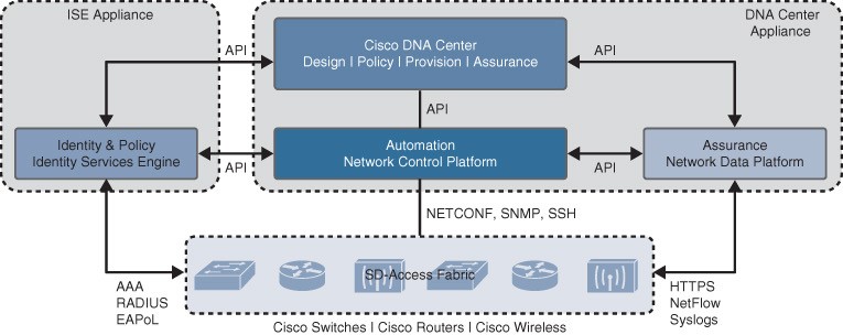
Figure 23-8 SD-Access Main Components
Controller Layer Subsystems
There are three main controller subsystems:
- Cisco Network Control Platform (NCP) – This is a subsystem integrated directly into Cisco DNA Center that provides all the underlay and fabric automation and orchestration services for the physical and network layers. NCP configures and manages Cisco network devices and then provides network automation status and other information to the management layer.
- Cisco Network Data Platform (NDP) – NDP is a data collection and analytics and assurance subsystem that is integrated directly into Cisco DNA Center. NDP analyzes and correlates various network events through multiple sources (such as NetFlow and Switched Port Analyzer [SPAN]) and identifies historical trends.
- Cisco Identity Services Engine (ISE) – The basic role of ISE is to provide all the identity and policy services for the physical layer and network layer. ISE provides network access control (NAC) and identity services for dynamic endpoint-to-group mapping and policy definition in a variety of ways.
Management Layer
The Cisco DNA Center management layer is the user interface/user experience (UI/UX) layer, where all the information from the other layers is presented to the user in the form of a centralized management dashboard. It is the intent-based networking aspect of Cisco DNA. The Cisco DNA design workflow provides all the tools needed to logically define the SDAccess fabric. The following are some of the Cisco DNA design tools:
- Network Hierarchy – Used to set up geolocation, building, and floorplan details and associate them with a unique site ID.
- Network Settings – Used to set up network servers (such as DNS, DHCP, and AAA), device credentials, IP management, and wireless settings.
- Image Repository – Used to manage the software images and/or maintenance updates, set version compliance, and download and deploy images.
- Network Profiles – Used to define LAN, WAN, and WLAN connection profiles (such as SSID) and apply them to one or more sites.
Cisco DNA Policy Workflow
The Cisco DNA policy workflow provides all the tools to logically define Cisco DNA policies. The following are some of the Cisco DNA policy tools:
- Dashboard – Used to monitor all the VNs, scalable groups, policies, and recent changes.
- Group-Based Access Control – Used to create group-based access control policies, which are the same as SGACLs. Cisco DNA Center integrates with Cisco ISE to simplify the process of creating and maintaining SGACLs.
- IP-Based Access Control – Used to create IP-based access control policy to control the traffic going into and coming out of a Cisco device in the same way that an ACL does.
- Application – Used to configure QoS in the network through application policies.
- Traffic Copy – Used to configure Encapsulated Remote Switched Port Analyzer (ERSPAN) to copy the IP traffic flow between two entities to a specified remote destination for monitoring or troubleshooting purposes.
- Virtual Network – Used to set up the virtual networks (or use the default VN) and associate various scalable groups
Cisco DNA Provision Workflow
The Cisco DNA provision workflow provides all the tools to deploy the Cisco SDAccess fabric. The following are some of the Cisco DNA provision tools:
- Devices – Used to assign devices to a site ID, confirm or update the software version, and provision the network underlay configurations.
- Fabrics – Used to set up the fabric domains (or use the default LAN fabric).
- Fabric Devices – Used to add devices to the fabric domain and specify device roles (such as control plane, border, edge, and WLC).
- Host Onboarding – Used to define the host authentication type (static or dynamic) and assign host pools (wired and wireless) to various VNs.