Understanding Basic Wireless Theory
basic theory behind RF signals, measuring & comparing the power of RF signals.

- Wireless signals travel as electromagnetic waves through the air from sender to receiver.

- Frequency: a fundamental property of electromagnetic waves through the air the waves involved in a wireless link.
Basic Wireless Concepts
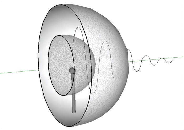
The sender sends an AC into an antenna, sets up moving electric and magnetic fields that propagate out and away from the antenna as traveling waves. 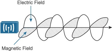
- The electric and magneticfields travel along together and at right angles to each other.
- The signal must keep changing (alternating), by cycling up and down, to keep the electric and magnetic fields cycling and pushing ever outward.
Basic Wireless Concepts
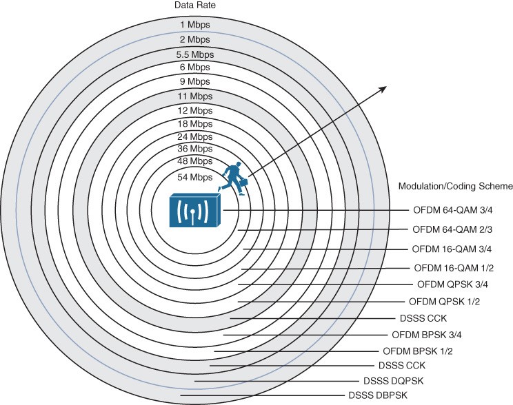
The waves produced from a tiny point antenna expand outward in a spherical shape. The waves eventually reach the receiver, in addition to many other locations in other directions. 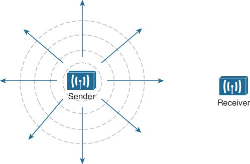
- At the receiving end, the process reversed.
- As the electromagnetic waves reach the receiver’s antenna, they induce an electrical signal.
- If everything works right, the received signal will be a reasonable copy of the original signal.
Understanding Frequency
• The number of cycles per second. 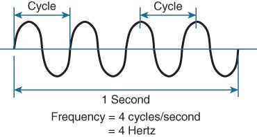
Frequency Unit Names
| Unit | Abbreviation | Meaning |
| Hertz | Hz | Cycles per second |
| Kilohertz | kHz | 1000 Hz |
| Megahertz | MHz | 1,000,000 Hz |
| Gigahertz | GHz | 1,000,000,000 Hz |
Continuous Frequency Spectrum
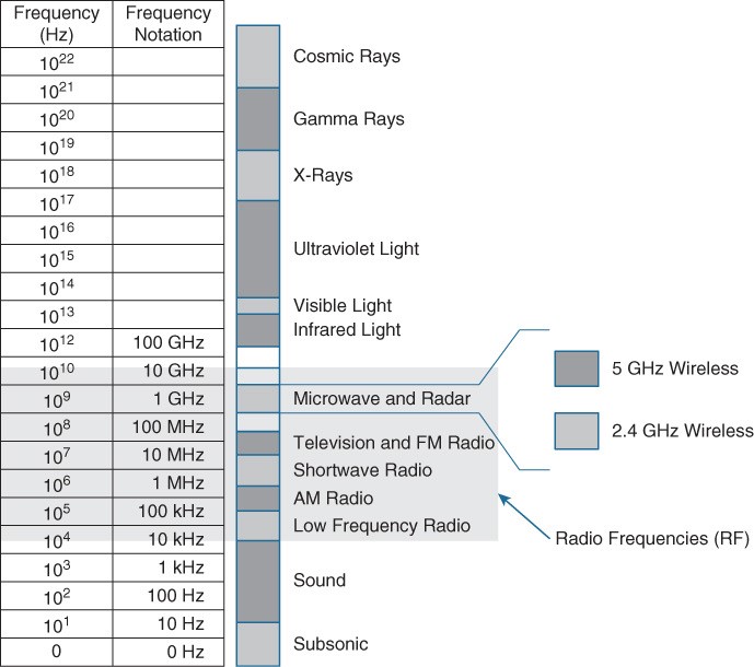
- The frequency range from 3 kHz -> 300 GHz called RF.
- It includes many different types, such as lowfrequency radio, AM, shortwave, TV, FM, microwave, radar.
Frequency Bands for Wireless LANs
- 2.400-2.4835 GHz (called 2.4 GHz band). q The other is 5 GHz band (5.150 and 5.825 GHz).
- The 5 GHz band actually contains four separate and distinct bands:
- 5.150 to 5.250 GHz
- 5.250 to 5.350 GHz
- 5.470 to 5.725 GHz
- 5.725 to 5.825 GHz
- Most of the 5 GHz bands are contiguous except for a gap between 5.350 and 5.470, cannot be used for wLANs. (conflict with weather radar).
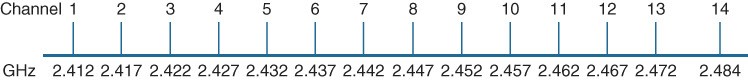
Understanding Frequency – Channels
- Frequency bands usually divided up into a number of distinct channels.
- Each channel known by a channel number, assigned to a specific frequency.
Understanding Frequency – Bandwidth
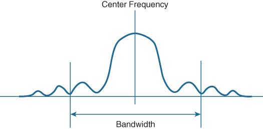
- The actual frequency range needed for the transmitted signal known as the signal bandwidth.
- Bandwidth refers to the width of frequency space required within the band.
- Wireless devices will use spectral mask to ignore parts fall outside the boundaries.
Understanding Frequency – Overlapping Channels
When the signal bandwidth is wider than the channel assignment, the signals overlap each other. Because of this, signals on adjacent channels cannot possibly coexist without interfering with each other. 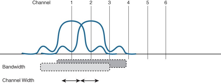 Signals must be placed on more distant channels to prevent overlapping -> limiting the number of usable channels in the band.
Understanding Phase
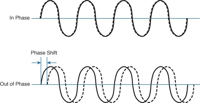
- RF signals are very dependent upon timing because they are always in motion.
- The phase of a signal is a measure of shift in time relative to the start of a cycle.
- When two signals produced at exactly the same time, their cycles match up (in phase).
- If one delayed from the other, the two are out of phase.
- Signals in phase tend to add together, whereas signals that are 180 degrees out of phase tend to cancel (triệt tiêu) each other.
Measuring Wavelength
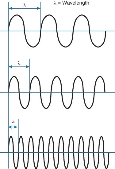
- The physical distance that a wave travels over one cycle.
- Designated by the lambda (λ).
- Wavelength decreases as the frequency increases. As the wave cycles get smaller, they cover less distance.
Understanding RF Power and dB

- The strength of an RF signal measured by its power, in Watt.

- When power measured in W or mW, it is considered to be an absolute power measurement.

- Because absolute power values can fall anywhere within a huge range, from a tiny number to hundreds, thousands, we use logarithmic functions to transform exponential ranges into linear.

- dB is a handy function that uses logarithms to compare one absolute measurement to another.

- dB originally developed to compare sound intensity levels, but it applies directly to power levels, too.
Understanding RF Power and dB
- Equation used to calculate a dB, P1 & P2: the absolute power levels of two sources:
![]()
- P2 represents the source of interest, P1: the reference value.
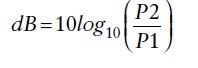
- The ratio or division form of the equation is the most commonly used in the wireless engineering world.
Understanding RF Power and dB
- Law of Zero: 0 dB: the two absolute power values are equal. The ratio is 1, log10(1) = 0.
- Law of 3s: 3 dB means that the power value is double the reference value; −3 dB means the power value is half the reference. When P2 is twice P1, the ratio is 2. 10log10(2) = 3 dB. When the ratio is 1/2, 10log10(1/2) = −3 dB.
- Law of 10s: A value of 10 dB means that the power value of interest is 10 times the reference value; a value of −10 dB means the power value of interest is 1/10 of the reference.
- •When P2 is 10 times P1, the ratio is 10. Therefore, 10log10(10) = 10 dB.
- •When P2 is one tenth of P1, the ratio is 1/10 and 10log10(1/10) = −10 dB.
Understanding RF Power and dB
| Power Change | dB Value |
| = | 0 dB |
| × 2 | +3 dB |
| / 2 | −3 dB |
| × 10 | +10 dB |
| / 10 | −10 dB |
Example of Computing dB
D and E have power levels 5 and 200 mW. Try to figure out a way to go from 5 to 200 using only × 2 or × 10 operations. 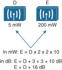
- Using the x2 and x10 operations, double 5 to get 10, then double 10 to 20. Multiply by 10 to reach 200 mW. (E=D x 2 x 2 x 10)
- Use the dB laws to replace the doubling and x10 with the dB equivalents.
- E=D + 3 + 3 + 10 dB or E=D + 16 dB
Free Space Path Loss
- Whenever an RF signal is transmitted from an antenna, its amplitude decreases as it travels through free space.
- Even if there are no obstacles in the path between the transmitter and receiver, the signal strength will weaken, known as free space path loss.
- Regardless of the antenna used, the amount of free space path loss through free space is consistent. Two facts:
- Free space path loss is an exponential function; the signal strength falls off quickly near the transmitter but more slowly farther away.
- The loss is a function of distance and frequency only.
Free space path loss is greater in the 5 GHz than it is in the 2.4 GHz. As the frequency increases, so does the loss in dB. 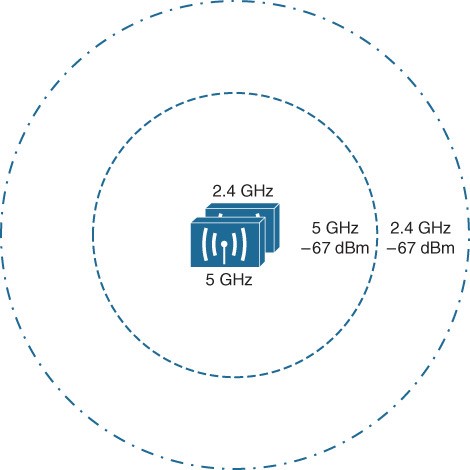
Power Levels at the Receiver
Receivers usually measure a signal’s power level according to the Received Signal Strength Indicator (RSSI). The RSSI defined in the 802.11 standard as 1-byte, value ranging from 0 (weak) to 255 (strong). The range of RSSI values can vary between hardware manufacturer.
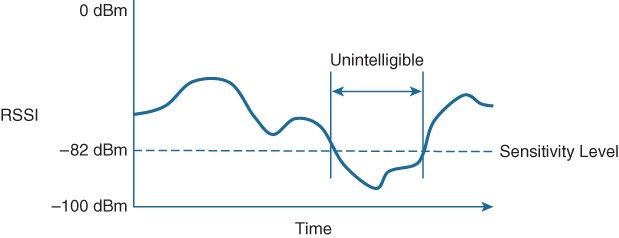
Every receiver has a sensitivity level, or a threshold that divides intelligible, useful signals from unintelligible ones. As long as a signal is received with a power level that is greater than the sensitivity level, the data from the signal can be understood correctly.
Power Levels at the Receiver
The RSSI focuses on the expected signal alone, without regard to any other signals that may also be received. All other signals received on the same frequency are simply viewed as noise. The noise level, or the average signal strength of the noise, called the noise floor.  The difference between the signal and the noise is called SNR, measured in dB. A higher SNR value preferred.
Other useful information: