Generic Routing Encapsulation (GRE) Tunnels
explains GRE and how to configure and verify GRE tunnels.
- tunneling protocol that provides connectivity to a wide variety of networklayer protocols by encapsulating and forwarding packets over an IP-based network.
- GRE can be used to tunnel traffic through a firewall or an ACL or to connect discontiguous networks.
- The most important application of GRE tunnels is that they can be used to create VPNs.
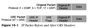
GRE Packet Headers
- When a router encapsulates a packet for a GRE tunnel, it adds new header information (known as encapsulation) to the packet. This new header contains the remote endpoint IP address as the destination.
- The new IP header information enables the packet to be routed between the two tunnel endpoints without inspection of the packet’s payload.
- When the packet reaches the remote tunnel endpoint, the GRE headers removed (known as de-encapsulation) and the original packet is forwarded out of the router.
GRE Tunnel Configuration
R1 and R2 are using their respective ISP routers as their default gateways to reach the internet. 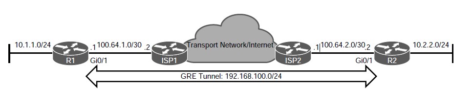 Figure 16-2 GRE Tunnel Topology Example 16-1 R1’s Routing Table Without GRE Tunnel
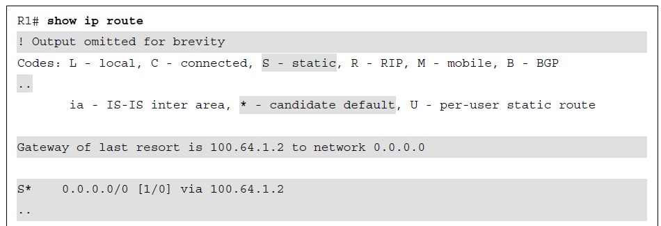
GRE Tunnel Configuration (Cont.)
- Step 1. Create the tunnel interface by interface tunnel tunnel-number.
- Step 2. Identify the local source of the tunnel by tunnel source {ip-address | interface-id}. The tunnel source can be a physical interface or a loopback interface.
- Step 3. Identify the remote destination IP address by tunnel destination ip-address.
- Step 4. Allocate an IP address to the tunnel interface ip address ip-address subnetmask.
- Step 5. (Optional) Define the tunnel bandwidth for use by QoS or for routing protocol metrics. Bandwidth is defined with the interface parameter command bandwidth [1-10000000], which is measured in kilobits per second.
- Step 6. (Optional) Specify a GRE tunnel keepalive with the interface parameter command keepalive [seconds [retries]]. The default timer is 10 seconds, with three retries. Tunnel keepalives ensure that bidirectional communication exists between tunnel endpoints to keep the line protocol up.
- Step 7. (Optional) Define the IP maximum transmission unit (MTU) for the tunnel interface. Specifying the IP MTU on the tunnel interface has the router perform the fragmentation in advance of the host having to detect and specify the packet MTU.
IP MTU is configured with the interface parameter command ip mtu mtu.
GRE Tunnel Configuration
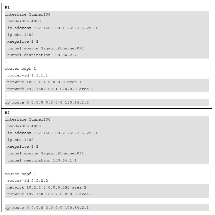
Example 16-2 provides a GRE tunnel configuration for R1 and R2, following the steps for GRE configuration listed earlier. With this configuration, R1 and R2 become direct OSPF neighbors over the GRE tunnel and learn each other’s routes.
GRE Tunnel Verification
The state of the GRE tunnel can be verified with the command show interface tunnel number. 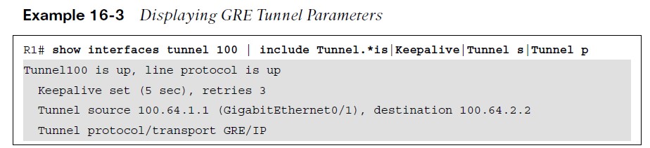
GRE Tunnel Verification
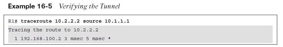
Additional commands to verify the status of a GRE tunnel include show ip route and traceroute. 
Problems with Overlay Networks
Recursive routing and outbound interface selection are two common problems with tunnel or overlay networks.
- Recursive routing can occur when the transport network is advertised into the same routing protocol that runs on the overlay network.
- Routers detect recursive route and generate syslog messages.
- Recursive routing problems are remediated by preventing the tunnel endpoint address from being advertised across the tunnel network.
Other useful information: