BGP Multihoming
reviews the methods of providing resiliency through redundant BGP connections, along with desired and undesired design considerations for Internet and MPLS connections (branch and data center).
- An organization must incorporate redundancies in the network architecture to ensure that there are not any single points of failure (SPOF).
- The simplest method of providing redundancy is to provide a second circuit.
- Adding a second circuit and establishing a second BGP session is known as BGP multihoming.
Resiliency in Service Providers
 By using a different SP, if one SP has problems in its network, network traffic can still flow across the other SP. In addition, adding more SPs means traffic can select an optimal path between devices due to the BGP best-path algorithm
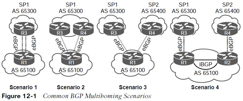
- Scenario 1: Same SP. This design accounts for link failures. However, a failure on either router or within SP1’s network results in a network failure.
- Scenario 2: Same SP. This design accounts for link failures, However, a failure on R1 or within SP1’s network results in a network failure.
- Scenario 3: Different SPs. This design accounts for link failures and failures in either SP’s network, and it can optimize routing traffic. However, a failure on R1 results in a network failure.
- Scenario 4: Different SPs. Design accounts for link failures and failures in either SP’s network, and it can optimize routing traffic. Also it accounts for network failure on the interior Network by having R1 and R2 form an iBGP session with each other.
Internet Transit Routing
Using BGP to connect with more than one SP, runs the risk of the autonomous system (AS) becoming a transit AS. 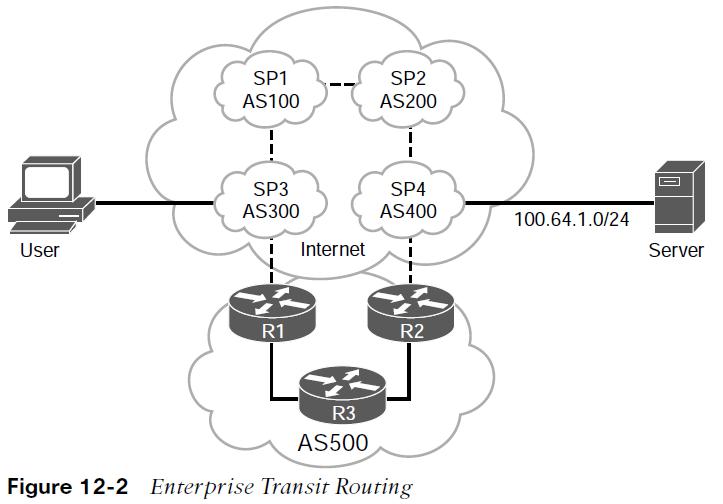 A user that connects to SP3 (AS 300) routes through the enterprise network (AS 500) to reach a server that attaches to SP4 (AS 400) because the AS_Path is much shorter than going through SP1 and SP2’s networks. The AS 500 network is providing transit routing to everyone on the Internet, which can saturate AS 500’s peering links. Instead of using the default BGP routing policy transit routing can be avoided by applying outbound BGP route policies that only allow for local BGP routes to be advertised to other AS.
Branch Transit Routing
Figure 12-3 shows a multihomed design. All the routers are configured to prefer the MPLS SP2 transport over the MPLS SP1 transport (active/passive). 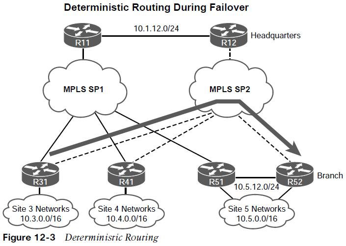
All the routers peer and advertise all the routes via eBGP to the SP routers. All the routers set the local preference for MPLS SP2 to a higher value to route traffic through it. The traffic between the sites uses the preferred SP network (MPLS SP2) in both directions. This simplifies troubleshooting when the traffic flow is symmetric (same path in both directions) as opposed to asymmetric forwarding (a different path for each direction). The path is considered deterministic when the flow between sites is predetermined and predictable.
Branch Transit Routing
Figure 12-4 shows a failure scenario with the R41 branch router providing transit connectivity between Site 3 and Site 5. Unplanned transit presents the following issues:
- The transit router’s circuits can become oversaturated.
- The routing patterns can become unpredictable and nondeterministic. In this scenario, traffic from R31 may flow through R41, but the return traffic may take a different return path. This prevents deterministic routing, and complicates troubleshooting.
Multihomed environments should be configured so that branch routers cannot act as transit routers. Transit routing can be avoided by configuring outbound route filtering at each branch site. Branch sites do not advertise what they learn from the WAN but advertise only networks that face the LAN. Note: Transit routing at the data center or other planned locations is normal in enterprise designs as they have accounted for the bandwidth. 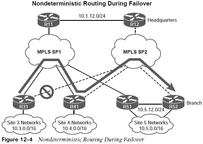 Other useful information: