About Lesson
OSPF Fundamentals
overview of communication between OSPF routers.
- is a nonproprietary Interior Gateway Protocol (IGP) that overcomes the deficiencies of other distance vector routing protocols and distributes routing information within a single OSPF routing domain.
- introduced variable-length subnet masking (VLSM), which supports classless routing, summarization, authentication, and external route tagging.
- There are two main versions of OSPF in production networks today: OSPFv2 which supports IPv4, OSPFv3 supports IPv6.
LSAs, LSDB,SPT
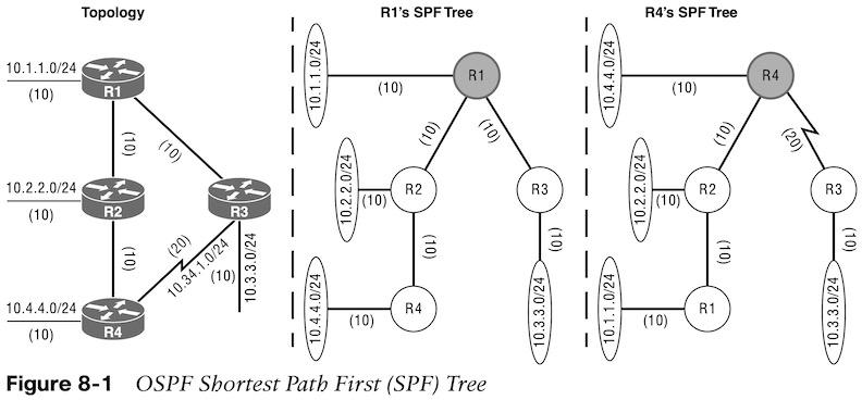
- OSPF sends link-state advertisements (LSAs) to neighboring routers. LSAs contain the link state and link metric. The received LSAs are stored in a local database called the link-state database (LSDB). The LSDB provides the topology of the network. The SPT contains all network destinations within the OSPF domain.
OSPF Architecture
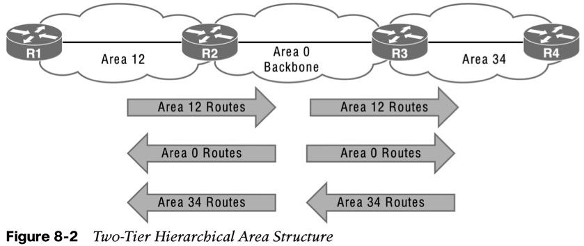
- OSPF uses multiple OSPF areas within the routing domain. OSPF uses a two-tier hierarchical architecture, where Area 0 is a special area known as the backbone, to which all other areas must connect. Nonbackbone areas advertise routes into the backbone. The backbone advertises routes into other nonbackbone areas.
- Figure 8-2 shows route advertisement into other areas. Area 12 routes are advertised to Area 0 and then into Area 34. Area 34 routes are advertised to Area 0 and then into Area 12. Area 0 routes are advertised into all other OSPF areas.
Inter-Router Communication
OSPF uses the assigned IPv4 protocol 89 and multicast addresses 224.0.0.5 (All routers) and 224.0.0.6 (DR routers) where possible to reduce unnecessary traffic.
| Type | Packet Name | Functional Overview |
| 1 | Hello | Discover and maintain neighbors. Packets are sent periodically on all OSPF interfaces to discover neighbors and ensure that other adjacentneighbors are still online. |
| 2 | Database description (DBD) or (DDP) | Summarize database contents. Packets are exchanged when an OSPF adjacency is formed. They describe the LSDB contents. |
| 3 | Link-state request (LSR) | Download databases. If a router thinks that part of its LSDB is stale, it requests part of a neighbor’s DB using this packet type. |
| 4 | Link-state update (LSU) | Update databases. This is an explicit LSA for a specific network link and normally is sent in direct response to an LSR. |
| 5 | Link-state ack | Flood acknowledgments. These are sent in response to LSA flooding, making flooding a reliable transport feature. |
OSPF Hello Packets
| Data Field | Description |
| Router ID (RID) | A unique 32-bit ID within an OSPF domain. |
| Authentication options | Between OSPF routers: none, clear text, or MD5 authentication. |
| Area ID | An interface’s OSPF area. A 32-bit number written in dotted- decimal format (0.0.1.0) or decimal (256). |
| Interface address mask | The interface’s primary IP address network mask. |
| Interface priority | The router interface priority for DR elections. |
| Hello interval | The time span, in seconds, that a router sends out hello packets. |
| Dead interval | The time span, in seconds, that a router waits to hear a hello from a neighbor router before it declares that router down. |
| DR and BDR | IP address of the DR and backup DR (BDR) for the network link. |
| Active neighbor | A list of OSPF neighbors on the network segment. A router must have received a hello from the neighbor within the dead interval. |
Neighbors
| State | Description |
| Down | The initial state of a neighbor relationship. Indicates that the router has not received any OSPF hello packets. |
| Attempt | Indicates that no information has been received recently, but the router is still attempting communication. |
| Init | Indicates that a hello packet has been received from another router, but bidirectional communication has not been established. |
| 2-Way | Bidirectional communication established. If a DR or BDR is needed, the election occurs during this state. |
| ExStart | The first state in forming an adjacency. Routers identify which router will be the master or slave for the LSDB synchronization. |
| Exchange | Routers are exchanging link states by using DBD packets. |
| Loading | LSRs sent to neighbor asking for more recent LSAs that have been discovered (but not received) in the Exchange state. |
| Full | Neighboring routers are fully adjacent. |
DR and BDR
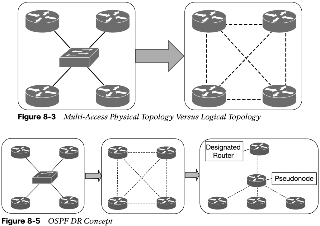
- If four routers share the same multi-access network, six OSPF adjacencies form, along with six occurrences of database flooding on a network. Figure 8-3 shows a simple four-router physical topology and the adjacencies established.
- Figure 8-5 shows how a DR simplifies a four-router topology with only three neighbor adjacencies.
Other useful information:
Join the conversation