Module Title: ACL Concepts Module Objective: Explain how ACLs are used as part of a network security policy.
| Topic Title | Topic Objective |
| Purpose of ACLs | Explain how ACLs filter traffic. |
| Wildcard Masks in ACLs | Explain how ACLs use wildcard masks. |
| Guidelines for ACL Creation | Explain how to create ACLs. |
| Types of IPv4 ACLs | Compare standard and extended IPv4 ACLs. |
Purpose of ACLs
What is an ACL?
An ACL is a series of IOS commands that are used to filter packets based on information found in the packet header. By default, a router does not have any ACLs configured. When an ACL is applied to an interface, the router performs the additional task of evaluating all network packets as they pass through the interface to determine if the packet can be forwarded.
- An ACL uses a sequential list of permit or deny statements, known as access control entries (ACEs).
Note: ACEs are also commonly called ACL statements.
- When network traffic passes through an interface configured with an ACL, the router compares the information within the packet against each ACE, in sequential order, to determine if the packet matches one of the ACEs. This process is called packet filtering.
Several tasks performed by routers require the use of ACLs to identify traffic:
- Limit network traffic to increase network performance
- Provide traffic flow control
- Provide a basic level of security for network access
- Filter traffic based on traffic type
- Screen hosts to permit or deny access to network services
- Provide priority to certain classes of network traffic
Packet Filtering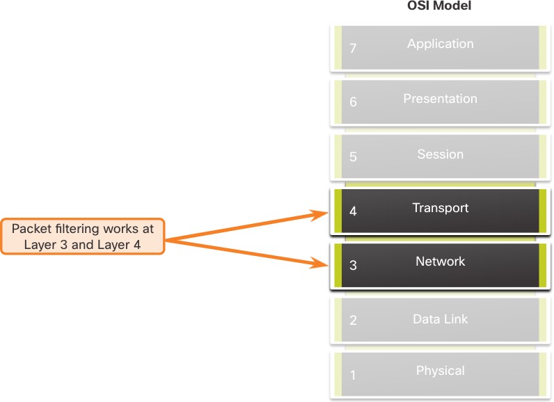 Packet filtering controls access to a network by analyzing the incoming and/or outgoing packets and forwarding them or discarding them based on given criteria.
- Packet filtering can occur at Layer 3 or Layer 4.
- Cisco routers support two types of ACLs:
- Standard ACLs – ACLs only filter at Layer 3 using the source IPv4 address only.
- Extended ACLs – ACLs filter at Layer 3 using the source and / or destination IPv4 address. They can also filter at Layer 4 using TCP, UDP ports, and optional protocol type information for finer control.
ACL Operation
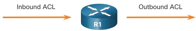
- ACLs define the set of rules that give added control for packets that enter inbound interfaces, packets that relay through the router, and packets that exit outbound interfaces of the router.
- ACLs can be configured to apply to inbound traffic and outbound traffic.
Note: ACLs do not act on packets that originate from the router itself.
- An inbound ACL filters packets before they are routed to the outbound interface. An inbound ACL is efficient because it saves the overhead of routing lookups if the packet is discarded.
- An outbound ACL filters packets after being routed, regardless of the inbound interface.
ACL Operation (Cont.)
When an ACL is applied to an interface, it follows a specific operating procedure. Here are the operational steps used when traffic has entered a router interface with an inbound standard IPv4 ACL configured:
- The router extracts the source IPv4 address from the packet header.
- The router starts at the top of the ACL and compares the source IPv4 address to each ACE in a sequential order.
- When a match is made, the router carries out the instruction, either permitting or denying the packet, and the remaining ACEs in the ACL, if any, are not analyzed.
- If the source IPv4 address does not match any ACEs in the ACL, the packet is discarded because there is an implicit deny ACE automatically applied to all ACLs.
The last ACE statement of an ACL is always an implicit deny that blocks all traffic. It is hidden and not displayed in the configuration. Note: An ACL must have at least one permit statement otherwise all traffic will be denied due to the implicit deny ACE statement.
Wildcard Masks in ACLs
Wildcard Mask Overview
A wildcard mask is similar to a subnet mask in that it uses the ANDing process to identify which bits in an IPv4 address to match. Unlike a subnet mask, in which binary 1 is equal to a match and binary 0 is not a match, in a wildcard mask, the reverse is true.
- An IPv4 ACE uses a 32-bit wildcard mask to determine which bits of the address to examine for a match.
- Wildcard masks use the following rules to match binary 1s and 0s:
- Wildcard mask bit 0 – Match the corresponding bit value in the address
- Wildcard mask bit 1 – Ignore the corresponding bit value in the address
| Wildcard Mask | Last Octet (in Binary) | Meaning (0 – match, 1 – ignore) |
| 0.0.0.0 | 00000000 | Match all octets. |
| 0.0.0.63 | 00111111 |
|
| 0.0.0.15 | 00001111 |
|
| 0.0.0.248 | 11111100 |
|
| 0.0.0.255 | 11111111 |
|
Wildcard Mask Types
Wildcard to Match a Host:
-
- Assume ACL 10 needs an ACE that only permits the host with IPv4 address 192.168.1.1. Recall that “0” equals a match and “1” equals ignore. To match a specific host IPv4 address, a wildcard mask consisting of all zeroes (i.e., 0.0.0.0) is required.
- When the ACE is processed, the wildcard mask will permit only the 192.168.1.1 address. The resulting ACE in ACL 10 would be access-list 10 permit 192.168.1.1 0.0.0.0.
| Decimal | Binary | |
| IPv4 address | 192.168.1.1 | 11000000.10101000.00000001.00000001 |
| Wildcard Mask | 0.0.0.0 | 00000000.00000000.00000000.00000000 |
| Permitted IPv4 Address | 192.168.1.1 | 11000000.10101000.00000001.00000001 |
Wildcard Mask to Match an IPv4 Subnet
-
- ACL 10 needs an ACE that permits all hosts in the 192.168.1.0/24 network. The wildcard mask 0.0.0.255 stipulates that the very first three octets must match exactly but the fourth octet does not.
- When processed, the wildcard mask 0.0.0.255 permits all hosts in the 192.168.1.0/24 network. The resulting ACE in ACL 10 would be access-list 10 permit 192.168.1.0 0.0.0.255.
| Decimal | Binary | |
| IPv4 address | 192.168.1.1 | 11000000.10101000.00000001.00000001 |
| Wildcard Mask | 0.0.0.255 | 00000000.00000000.00000000.11111111 |
| Permitted IPv4 Address | 192.168.1.0/24 | 11000000.10101000.00000001.00000000 |
Wildcard Mask to Match an IPv4 Address Range
-
- ACL 10 needs an ACE that permits all hosts in the 192.168.16.0/24, 192.168.17.0/24,…, 192.168.31.0/24 networks.
-
- When processed, the wildcard mask 0.0.15.255 permits all hosts in the 192.168.16.0/24 to 192.168.31.0/24 networks. The resulting ACE in ACL 10 would be access-list 10 permit 192.168.16.0 0.0.15.255.
| Decimal | Binary | |
| IPv4 address | 192.168.16.0 | 11000000.10101000.00010000.00000000 |
| Wildcard Mask | 0.0.15.255 | 00000000.00000000.00001111.11111111 |
| Permitted IPv4 Address | 192.168.16.0/24 to 192.168.31.0/24 | 11000000.10101000.00010000.00000000 11000000.10101000.00011111.00000000 |
Wildcard Mask Calculation
Calculating wildcard masks can be challenging. One shortcut method is to subtract the subnet mask from 255.255.255.255. Some examples:
-
- Assume you wanted an ACE in ACL 10 to permit access to all users in the 192.168.3.0/24 network. To calculate the wildcard mask, subtract the subnet mask (255.255.255.0) from 255.255.255.255. This produces the wildcard mask 0.0.0.255. The ACE would be access-list 10 permit 192.168.3.0 0.0.0.255.
- Assume you wanted an ACE in ACL 10 to permit network access for the 14 users in the subnet 192.168.3.32/28. Subtract the subnet (i.e., 255.255.255.240) from 255.255.255.255. This produces the wildcard mask 0.0.0.15. The ACE would be access-list 10 permit 192.168.3.32 0.0.0.15.
-
- Assume you needed an ACE in ACL 10 to permit only networks 192.168.10.0 and 192.168.11.0. These two networks could be summarized as 192.168.10.0/23 which is a subnet mask of 255.255.254.0. Subtract 255.255.254.0 subnet mask from 255.255.255.255. This produces the wildcard mask 0.0.1.255. The ACE would be access-list 10 permit 192.168.10.0 0.0.1.255.
Wildcard Mask Keywords
The Cisco IOS provides two keywords to identify the most common uses of wildcard masking. The two keywords are:
-
- host – This keyword substitutes for the 0.0.0.0 mask. This mask states that all IPv4 address bits must match to filter just one host address.
- any – This keyword substitutes for the 255.255.255.255 mask. This mask says to ignore the entire IPv4 address or to accept any addresses.
Guidelines for ACL Creation
Limited Number of ACLs per Interface
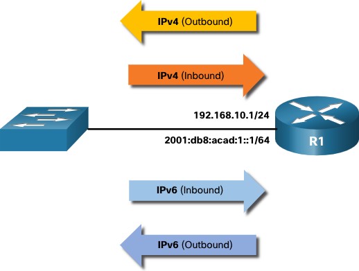
There is a limit on the number of ACLs that can be applied on a router interface. For example, a dual-stacked (i.e, IPv4 and IPv6) router interface can have up to four ACLs applied, as shown in the figure. Specifically, a router interface can have:
-
-
- One outbound IPv4 ACL.
- One inbound IPv4 ACL.
- One inbound IPv6 ACL.
- One outbound IPv6 ACL.
-
Note: ACLs do not have to be configured in both directions. The number of ACLs and their direction applied to the interface will depend on the security policy of the organization.
ACL Best Practices
Using ACLs requires attention to detail and great care. Mistakes can be costly in terms of downtime, troubleshooting efforts, and poor network service. Basic planning is required before configuring an ACL.
| Guideline | Benefit |
| Base ACLs on the organizational security policies. | This will ensure you implement organizational security guidelines. |
| Write out what you want the ACL to do. | This will help you avoid inadvertently creating potential access problems. |
| Use a text editor to create, edit, and save all of your ACLs. | This will help you create a library of reusable ACLs. |
| Document the ACLs using the remark command. | This will help you (and others) understand the purpose of an ACE. |
| Test the ACLs on a development network before implementing them on a production network. | This will help you avoid costly errors. |
Types of IPv4 ACLs
Standard and Extended ACLs
There are two types of IPv4 ACLs:
-
-
- Standard ACLs – These permit or deny packets based only on the source IPv4 address.
- Extended ACLs – These permit or deny packets based on the source IPv4 address and destination IPv4 address, protocol type, source and destination TCP or UDP ports and more.
-
Numbered and Named ACLs
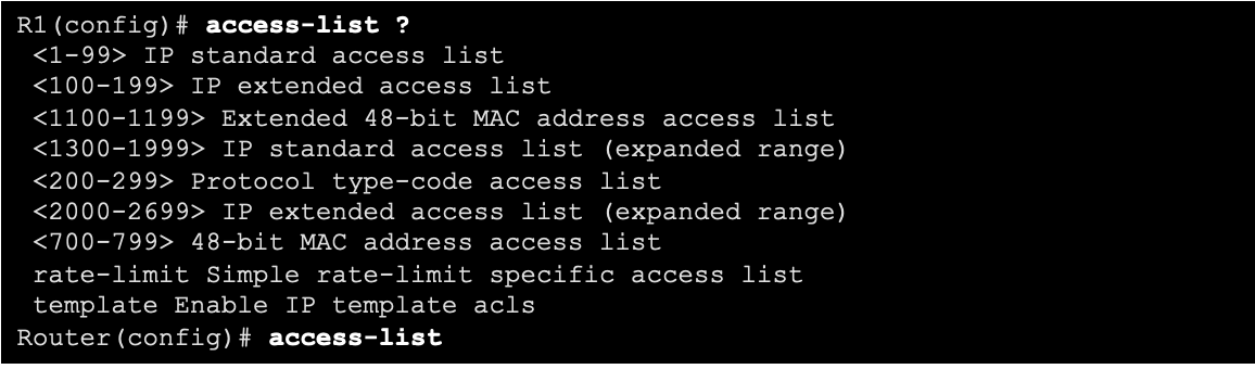
Numbered ACLs
- ACLs numbered 1-99, or 1300-1999 are standard ACLs, while ACLs numbered 100- 199, or 2000-2699 are extended ACLs.
Named ACLs
- Named ACLs are the preferred method to use when configuring ACLs. Specifically, standard and extended ACLs can be named to provide information about the purpose of the ACL. For example, naming an extended ACL FTP-FILTER is far better than having a numbered ACL 100.
- The ip access-list global configuration command is used to create a named ACL, as shown in the following example.
R1(config)# ip access-list extended FTP-FILTER 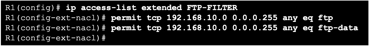
Where to Place ACLs
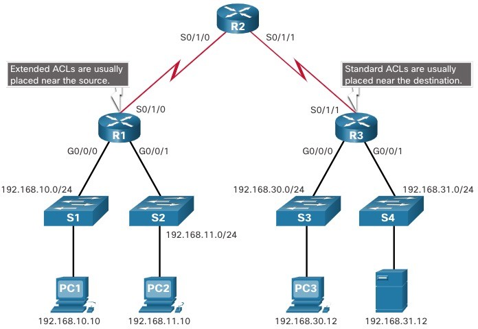
- Every ACL should be placed where it has the greatest impact on efficiency.
- Extended ACLs should be located as close as possible to the source of the traffic to be filtered.
- Standard ACLs should be located as close to the destination as possible.
| Factors Influencing ACL Placement | Explanation |
| The extent of organizational control | Placement of the ACL can depend on whether or not the organization has control of both the source and destination networks. |
| Bandwidth of the networks involved | It may be desirable to filter unwanted traffic at the source to prevent transmission of bandwidth-consuming traffic. |
| Ease of configuration |
|
Standard ACL Placement Example
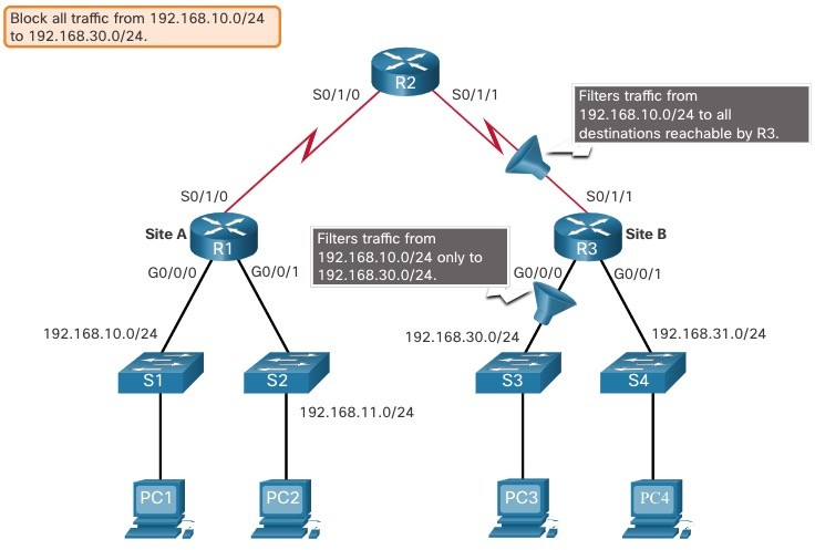 In the figure, the administrator wants to prevent traffic originating in the 192.168.10.0/24 network from reaching the 192.168.30.0/24 network. Following the basic placement guidelines, the administrator would place a standard ACL on router R3.
 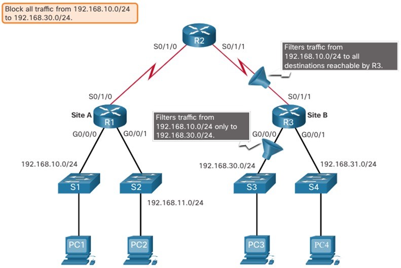 There are two possible interfaces on R3 to apply the standard ACL:
- R3 S0/1/1 interface (inbound) – The standard ACL can be applied inbound on the R3 S0/1/1 interface to deny traffic from .10 network. However, it would also filter .10 traffic to the 192.168.31.0/24 (.31 in this example) network. Therefore, the standard ACL should not be applied to this interface.
- R3 G0/0 interface (outbound) – The standard ACL can be applied outbound on the R3 G0/0/0 interface. This will not affect other networks that are reachable by R3. Packets from .10 network will still be able to reach the .31 network. This is the best interface to place the standard ACL to meet the traffic requirements.
Extended ACL Placement Example

- Extended ACLs should be located as close to the source as possible.
- However, the organization can only place ACLs on devices that they control. Therefore, the extended ACL placement must be determined in the context of where organizational control extends.
- In the figure, for example, Company A wants to deny Telnet and FTP traffic to Company B’s 192.168.30.0/24 network from their 192.168.11.0/24 network, while permitting all other traffic.
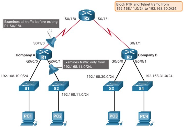 An extended ACL on R3 would accomplish the task, but the administrator does not control R3. In addition, this solution allows unwanted traffic to cross the entire network, only to be blocked at the destination. The solution is to place an extended ACL on R1 that specifies both source and destination addresses. There are two possible interfaces on R1 to apply the extended ACL:
- R1 S0/1/0 interface (outbound) – The extended ACL can be applied outbound on the S0/1/0 interface. This solution will process all packets leaving R1 including packets from 192.168.10.0/24.
- R1 G0/0/1 interface (inbound) – The extended ACL can be applied inbound on the G0/0/1 and only packets from the 192.168.11.0/24 network are subject to ACL processing on R1. Because the filter is to be limited to only those packets leaving the 192.168.11.0/24 network, applying the extended ACL to G0/1 is the best solution.